AVR Programmer
October 2013
What follows is based on my own very limited experience with ATMEL microprocessors and will, no doubt, need modifying in the future in the light of additional knowledge.
The ATMEL In-System Programming Methodology
ATMEL have a comprehensive guide to their In-System Programming so what follows is a quick summary as I understand the system.The system uses the microprocessor's normal three-wire SPI bus (MOSI, MISO and SCK) to provide in-circuit programming by tri-stating (or, effectively, isolating from any other circuitry) all the chip's other IO pins during programming. This is achieved by holding the chip's RESET pin active (low) during the entire programming operation.
The programmer acts as Master on the SPI bus, so the timing of holding the RESET pin low is most-easily achieved by the programmer. Therefore, in addition to the three SPI lines between the programmer and the "target" chip, a fourth line from the programmer is used to control the RESET pin.
Thanks to work by David A. Mellis, Randall Bohn, Randall Bohn and others, in the Arduino environment, all this is taken care of for us with a sketch called ArduinoISP to be found in the Examples folder.
As the target microprocessor and an In-System Programmer are usually physically separate entities, a fifth line (Ground) is also required between them. The ATMEL AVR guidelines allow flexibility in how the target chip is powered. In my programmer, both programmer and target chip are on the same printed circuit board. As the power comes from the PC's USB port, that power is used to supply both the programmer and the target chip. A PCB-mounted slide swich can disconnect power from the target chip, if required, without it being necessary to power-down the entire programmer.
An outbound ISP header is provided on the programmer to enable it to be used as a "true" In-System Programmer. The header is 'outbound' in that the RESET connection (on header pin 5) is an outbound signal to the target's RESET input.
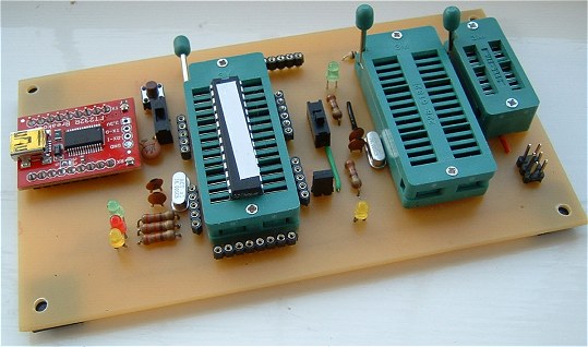
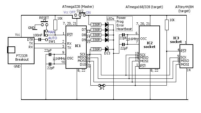
The Programmer Circuit
|
The FT232R USB to Serial converter supplies 5 volts to the Programmer from the computer's USB socket. There are several different
USB to Serial converters available, all of which do more or less the same job. I've used the Sparkfun
Breakout Board for FT232RL for this project
but it was
necessary to desolder the 3.3 volt solder bridge and bridge the 5 volt pads instead. It's shown on the schematic but is a bit
hard to spot unless you're aware of it. It's also necessary to solder the two 9-way male header strips to the board. The driver is available from the FTDI website although I found that allowing Windows to search the internet automatically successfully found, downloaded and installed the correct driver (in both XP and Windows 7). I've used a BV104 breakout board made by ByVac successfully in other projects so it really comes down to personal choice. | 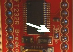 |
I've connected a yellow LED to the ATmega328's pin 19 (what would be the Arduino's "Hello World digitalPin 13"). I've also wired LEDs as recommended in the ArduinoISP sketch:
// Put an LED (with resistor) on the following pins:
// 9: Heartbeat - shows the programmer is running
// 8: Error - Lights up if something goes wrong (use red if that makes sense)
// 7: Programming - In communication with the slave
A fifth LED shows when switch SW2 is supplying power to the "target" sockets.
Switch SW1 enables the Master's RESET to be controlled manually, with the PCB-mounted tactile push button switch, or automatically by using the DTR signal from the RS232R breakout board (The ByVac breakout board has a similar connection available). It's envisaged that the Master will require re-programming from time to time; for example, to run the Bootloader Sketch instead of ArduinoISP. Once the new sketch is in place, SW1 should be switched to the Manual position to prevent the ATmega328 resetting itself at inconvenient moments.