Using The Programmer
Installing A Bootloader
A simple test for the finished programmer is to burn in the Arduino Bootloader.The bootloader is just a small program which permanently resides on the ATmega328 to make it easy to upload programs to the chip using the USB serial port in conjunction with the Arduino IDE.
I've not yet had any success with the Burn Bootloader option from the Arduino IDE's Tools menu so prefer, instead to use the "OptiLoader" method described on another webpage - Arduino Bootloader.
Of course, setting it all up is now a lot simpler as it's just a case of dropping a blank chip into the "target" zero insertion force socket:
- Select Auto Reset on the programmer (SW1 down).
- Ensure the Master ATmega328 is in place and the zero insertion force socket's lever is down.
- Open the Arduino IDE, load the OptiLoader sketch and upload it to the Master.
- Make sure SW2 is OFF (up), insert the target ATmega328 and slide SW2 to ON (down).
- Open the Arduino IDE Serial Monitor to initiate a reset.
- The Serial Monitor screen shows the progress and the job is done.
When you think about the "Installing A Bootloader" procedure, it raises a couple of questions: As the blank chip has no bootloader, we can't upload the bootloader using the USB serial port. And exaclty where is the bootloader code that we're going to upload?
The answer to the first question is that the OptiLoader sketch uses the SPI protocol between the Master ATmega 328 and the bootloader's "recipient" (the target). Remember from page 1 that the ATMEL chip is still able to communicate over the SPI bus even when the RESET line is held low. So OptiLoader uses SPI to transfer the bootloader machine code into the target.
Where does the machine code come from? Well, if you look at the OptiLoader sketch, you'll see it at the bottom of the sketch as an "image" destined for the Master's Flash memory. It's copied to the Master's memory when the sketch is initially uploaded and then it's copied, by SPI, from there to the target. The Master, of course, can use USB serial to receive the OptiLoader sketch (and the image) in the first place because it does have a bootloader. Clever!
Uploading a program to a chip without a bootloader
The first obvious question is why would you want to do this? Well, the bootloader is just a 'trick' to make it easy to upload programs to the ATmega328 using the USB serial port. It takes up memory space and it slows down a program starting when power is applied to the chip because the bootloader code needs to determine whether a new upload is about to take place.
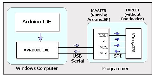
This diagram shows the process involved in uploading a program from the Arduino IDE to the target ATmega328 chip without using a bootloader.
Steps 1, 2 and 3 need only be done once.
- The first step is to use an ATmega328 which does contain a bootloader into the programmer's Master socket.
- In the Arduino IDE, load the sketch ArduinoISP from Files | Examples.
- Make sure SW1 on the programmer is set to 'Auto' and upload ArduinoISP to the Master ATmega328.
As ArduinoISP can remain in the Master chip more-or-less permanently, it's worth labelling it as such. - Switch SW1 to 'manual' to prevent the Master resetting itself and SW2 to 'Off'.
- Place a blank ATmega328 (one without a bootloader) into the 'Target' socket and switch SW2 to 'On'.
- In the Arduino IDE, from the Tools | Programmer menu, select Arduino as ISP.
- In the Arduino IDE, make sure the correct board is selected in the Tools | Board menu. 'Arduino Uno' for ATmega328
chips.
- Load whichever sketch you want to program the 'target' with into the Arduino IDE and click the Upload button.
Alternatively use the Sketch | Upload menu item (or Ctrl+U).
Note: In later versions of the Arduino IDE, click Upload Using Programmer from the Sketch menu (or Ctrl+Shift+U).
The 'README' included in the downloaded zip package contains full instructions for installing it into the Arduino IDE.
Make sure to select the correct board in step 7 above. Attiny84 @ 1MHz (internal ocillator; BOD disabled) ensures the correct timing for the Arduino delay() function.
Without a crystal the ATtiny84 runs at 8MHz but, by default, is divided by 8 internally. To run the chip at 8MHz and ensure functions such as delay() run with the correct timing it's necessary to:
- Select Attiny84 @ 8MHz (internal ocillator; BOD disabled) from the Boards menu and then select Tools | Burn Bootloader.
- Wait until it's completed and then upload the sketch and the timings will now be correct.
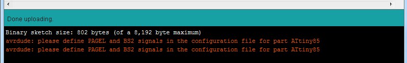
Incidentally, uploading to these chips always produces the following error(s), however the upload is successful.