A stand-alone Arduino
Elsewhere on my website, I show details of a Video Switcher which can be controlled using the computer's parallel port. Unfortunately, fewer PCs are fitted with parallel pors these days and, for a laptop, it's not really an option so the need to control the Switcher through a USB port became important. The Video Switcher only needs three digital inputs so, although the PICAXE range of Microcontrollers would probably provide a chip with a more economical use of pins, the Arduino seems easier to interface with a standard USB cable and it's a useful enough project to justify building a cut down stand-alone Arduino.
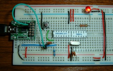
The Breadboard
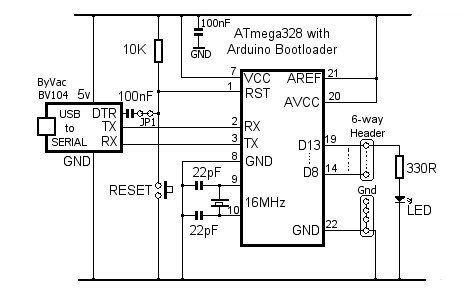
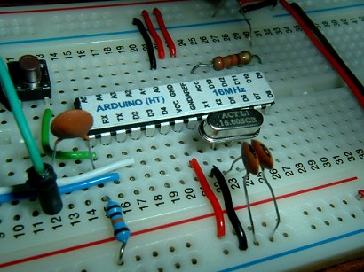
A stand-alone Arduino can conveniently be divided into two parts: The ATMega328 with its associated support components and the USB-to-Serial interface needed to upload sketches and provide the serial communication that was to replace the parallel port. I'd decided from the outset to use an ATmega328 with the Arduino bootloader already programmed in and not to complicate things by using a 'blank' chip.The 'associated support components' I mentioned above consist of a 16 MHz crystal, two 22pF capacitors and a tactile switch for the 'Reset' facility.
I bought the pre-programmed ATmega328 and the other components from HobbyTronics as they're based relatively locally to me (in the UK at least!). The 328 has a convenient pinout label already attached!
The Circuit
 |  |
 |  |
|
The USB to Serial converter supplies 5 volts to the Arduino from the computer's USB socket. There are several different
USB to Serial converters available, all of which do more or less the same job. I found the Sparkfun
Breakout Board for FT232RL (shown to the right) a bit fiddly to handle and it was
necessary to desolder the 3.3 volt solder bridge and bridge the 5 volt pads instead. It's shown on the schematic but is a bit
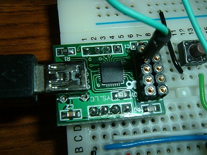
hard to spot unless you're aware of it. It's also necessary to solder the two 9-way male header strips to the board. I used a BV104 breakout board made by ByVac (shown above) which is described as a "Silicon Labs Low Cost USB to serial bridge". It comes with the two 4-way male headers already attached and works out about 2.50 UKP cheaper than Sparkfun's. It's also only about 2/3rds the size of the Sparkfun board which is useful if space is a problem. | 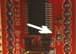 |
I fitted the two rows of female sockets which you can see in the photo (above left) because, during development, I wanted access to the standard serial signal lines - especially the DTR connection to provide optional "Auto Reset" for the ATMega328 when uploading sketches (the green "fly lead" in the photos). It's not necessary to fit these sockets in the finalized PCB version of the DIY Arduino.
The auto-reset can cause some problems by initiating a reset when you connect other USB devices to the same USB Hub - hence the flying lead. The finalized stand-alone Arduino PCB will use a header and jumper to disconnect the auto-reset once a sketch is uploaded.
Drivers
I'm running Windows 7 (64-bit) and was pleasantly surprized to discover that both the Sparkfun board and the ByVac board were recognised by the Operating System and drivers were installed automatically. The Sparkfun board's driver shows FTDI as the manufacturer and the ByVac board shows up as "Silicon Labs CP210x USB to UART Bridge".When I tried the finished project on my laptop, which runs XP, XP did what it does best and complained about the missing drivers. Feeling a bit lazy (or lucky), I asked it to search on the internet for suitable drivers and, to my amazement, it successfully located and installed the correct Silicon Labs driver!
Drivers for both boards are available on the corresponding manufacturer's websites if you're not so lucky and you do need to install them manually.
Meanwhile, back at the breadboard stage, having tested the circuit successfully on the breadboard, it was time to get designing the final printed circuit board.......