Arduino Bootloader
The price difference between an ATmega328 complete with the bootloader and one without is about 1.50UKP which, although not that great, it soon adds up once the Arduino bug bites and you start making your own Arduino clones.The idea of burning the bootloader oneself using an Arduino as the programmer is a bit daunting for fear of ending up with two non-working ATmega328s but, thanks to the work of others, it turns out to be relatively easy.
The Hardware
I recommend building a "bare-bones" Arduino on a breadboard on which to mount the "target" ATmega328 (ie, the one about to have the bootloader burnt in). This makes it much easier to deal with any issues about the auto-reset if an Arduino board is used.Besides an Arduino we're going to use as the programmer and the ATmega328 that we're going to program with the bootloader, we also need a handful of support components:
- 1 x 10K 1/8 watt resistor.
- 2 x 22pF capacitors.
- 1 x 16 MHz crystal.
- 1 x Breadboard.
- hookup wire.
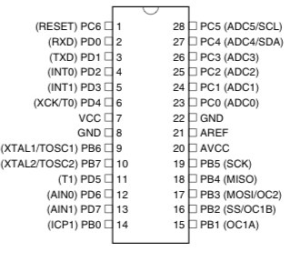
The ATmega328 pinout
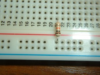 |
Begin by inserting a 10K resistor from the breadboard's 5 volt bus at about row 21, as shown here. This will mark the ATMega328's Pin 1 - its RESET pin. Pulling this pin high (ie to +5 volts) through the 10K resistor will stop any uncertainty about the pin's "state" and will prevent it resetting the chip at an inconvenient moment. The resistor is also a useful "reference point" for when we insert the other few components we need to build the minimal Arduino clone.
|
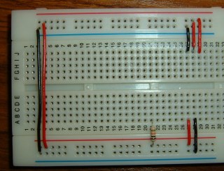 |
Now that we know where the ATmega328's pin 1 will be, we can add the chip's +5 volts and ground
connections.
The main +5 volts is on pin 7. Since we inserted the 10K resistor for pin 1 at the breadboard's row 21, it's easy to work out that the +5 volt pin will be at breadboard row 27. Next door, at pin 8, we can insert the chip's ground connection. Looking at the ATMega328's pinout drawing above, we can see that there's another ground connection on the other side of the chip, directly opposite pin 7. So, we can easily pinpoint that location and add a ground wire. On the same side, there are two more power connections (for the Analogue funtions in the chip). We can just tie those to the +5 volt bus for now. And finally, as we've used both edges of the breadboard's power buses, we need to join them together - the two long vertical wires in this picture. |
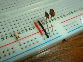 |
Next we need to insert the two 22pF capacitors between the two Crystal Oscillator pins on the ATmega328 and the
breadboard's Ground bus - as shown here. The ATmega328's crystal oscillator pins are pins 9 and 10. Nice and easy to locate right alongside the ground connection at pin 8.
|
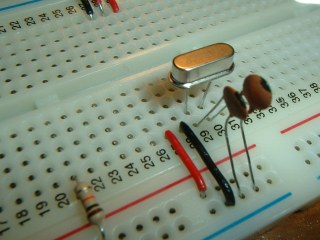 |
The last component to go in, before the chip itself, is the 16MHz crystal. The pin-spacing on crystals is usually wider than across
two rows on the breadboard so you'll need to bend them inwards slightly. Make sure the crystal case isn't
touching a lead of either of the capacitors.
|
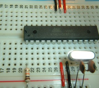 |
And finally, the ATmega328. Pin 1 is aligned with our 10K resistor on breadboard row 21. It sits across the trough in the breadboard and everything else falls into place! The breadboard will get its power from the Arduino that's going to be doing the programming, so connecting the Arduino to the breadboard is the next step (nearly!)..... |