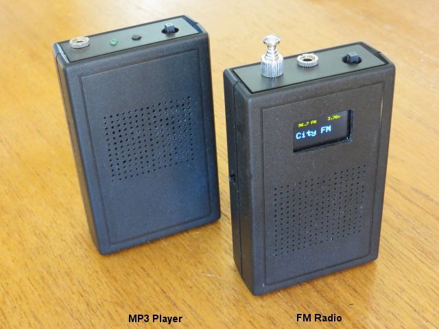
Si4703 Pocket FM Radio
Building this radio was a bit of a challenge because I wanted to fit it into an identical case to the one I used for my Poratble MP3 Player so, although similar to my Garden Radio, it is more portable and easily fits in a pocket.
The radio is built around the SparkFun Si4703 FM Tuner Basic Breakout rather than what Sparkfun now call the Evaluation breakout board.
The Basic breakout has no on-board audio amplifier or headphone socket, and is about half the size of the usual Si4703 breakout board. - unfortunately there don't appear to be any cheap Chinese clones available for this board so it does work out a bit more expensive.
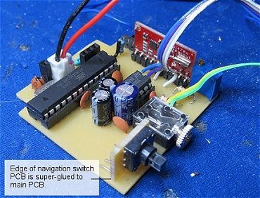
The other main differences between this project and the "Garden Radio" are the use of a small OLED display (instead of the Nokia 5110 LCD) and a 5-way 'navigation switch' for channel and volume selection (instead of a rotary encoder for channel selection and a standard potentiometer for the volume control).
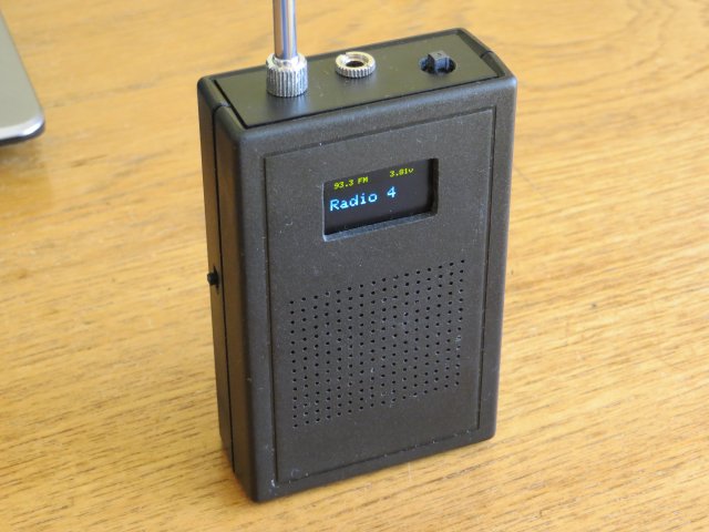
I used a 10" (25cm) telescopic antenna which retracts into the enclosure. With about 6" of extra wire tucked up inside the enclosure before connecting to the antenna, it works very well with reasonably strong radio signals but a longer aerial may be better. There is very little clearance around the antenna so a thicker one with more sections may be at risk of touching either the loudspeaker in front of it or components on the main PCB behind it.
The Circuit
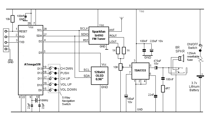
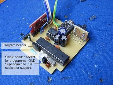
The ATmega328 RESET, RXD and TXD pins, together with GND, are brought out to a header socket for connecting to the programming hardware. I use a separate RS232-to-TTL converter, such as this one.
The 5 way navigation switch is connected to the ATmega328 digital pins D9 to D13.
The ATmega328 controls the Si4703 FM Tuner and drives the 128x64 0.96" OLED display. Both the tuner and the display are I2C devices.
As the OLED display is an I2C device, it is connected to ATmega328 pins A5 and A4 (SCL and SDA respectively). D3 is configured as a digital output and is used to switch power to the display.
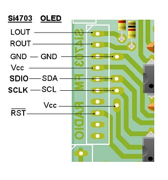
Analogue pins A5 and A4 (SCL and SDA) are also assigned to the Si4703 tuner (SCLK and SDIO). D2 is used to reset the tuner. Left and Right audio channels are picked up from the 'LOUT' and 'ROUT' connections on the edge of the tuner breakout board, combined into mono through the two 1K resistors and applied to the 'hot' end of a 10K preset potentiometer, the slider of which feeds the audio input of a TDA7233 low voltage audio amplifier.
Additionally, the ATmega328 software forces the Si4703 to receive in mono as there is some reduction in signal noise in poor reception areas and there is no point in struggling to receive in stereo only for the hardware to combine left and right channels anyway.
The Si4703 Basic breakout has a separate pin connection for the antenna as there is obviously no provision for the ground lead in a headphone cable to act as the aerial as it does in the Evaluation board.
The radio's volume is adjusted in software via the 5-way navigation switch using the Si4703's internal volume control register - the 10k preset is used to set the maximum volume to prevent clipping and distortion.
Operating at around 3.5 volts, the TDA7233 amplifier provides about 85 mW of audio power into an 8 ohm loudspeaker. The circuitry around the TDA7233 is taken directly from the datasheet. The whole project takes around 35mA at a reasonable volume level.
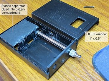
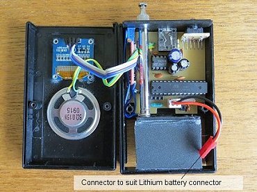
As the loudspeaker encroaches into the enclosure's battery compartment, there isn't enough space for a PP3 so I've used a 1000mAh Lithium-Polymer battery which neatly fits into the battery compartment designed for the PP3 battery but is only half the thickness. As Lithium batteries can deliver a LOT of current in the event of a fault, I've included a 125mA resettable fuse.
I super-glued a piece of plastic to separate the battery compartment into two sections so that the battery isn't resting on the loudspeaker.
The specified lithium polymer battery is protected against over-discharging but, as an extra precaution, the display will reduce brightness and display "LOW BATT" in a smaller font size (instead of the radio station name) if the battery voltage falls below the 'lowVoltsWarning' value (defined as 3.15 volts). If the voltage continues to fall, at 'lowVoltsCutOff' (3.10 volts), power to the OLED display is cut off, the Si4703 tuner is switched to 'powerdown' mode in software and the ATmega328 enters 'Sleep' mode. In this state, the entire project takes about 5mA.
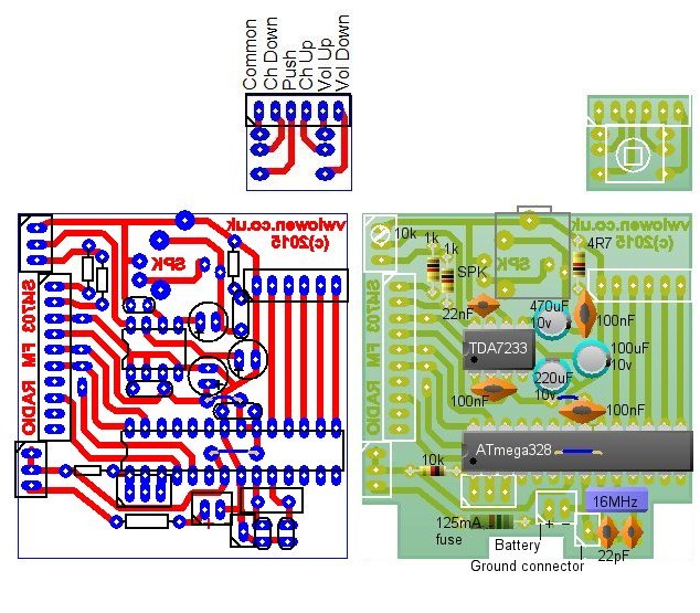
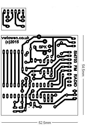
PCB Layout
Download Circuit Wizard PCB Layout.
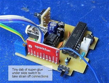
Construction
Main Components
| Sparkfun Si4703 Basic Breakout Board | Sparkfun, Pimoroni, Cool Components |
| 0.96" two-colour OLED display | eBay, Banggood |
| 1" x 2.4" x 3.8" Enclosure | Farnell |
| 5-way Navigation Switch (ALPS - SKQUCAA010) | Farnell, CPC, ebay |
| 3.5mm switched stereo socket | Farnell |
| Miniature right-angle SPDT PCB mounting slide switch | ebay |
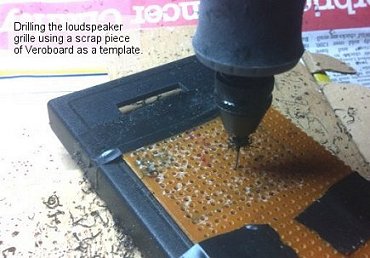
| KDMG36008 ~ 36mm dia. 8 ohm 0.15W loudspeaker (very low profile) | Farnell, ebay |
| 10" x 5-section telescopic antenna | ? Spares Box |
| 1000mAh Lithium Polymer battery (protected) 47mm x 28mm x 7mm | eBay |
The ATmega328 'sketch'
Si4703 Programming GuideSi4703 Datasheet & Register Summary
5-way navigation switch left and right is channel down and up respectively.
5-way navigation switch up and down is volume up and down.
Press and release the navigation switch to dim or un-dim the display.
Press and hold the navigation switch during power-up, to enable or disable the display's 15 second auto-off.
Arduino Libraries:
SparkFunSi4703.h
Adafruit_GFX.h
Adafruit_SSD1306.h
LowPower.h
Note that the Arduino sketch, uses an Adafruit OLED library for a slightly different display and the I2C register address shown in the Adafruit examples is different from the address we need to use for the imported device from eBay or BangGood (0x3c).
The Si4703 tuner's I2C address is 0x10. We need to know this for the Si4703 'Force Mono' and 'Powerdown' operations because we have to write to the Si4703 register directly as those functions aren't available in the Arduino Si4703_Breakout library.
#include <SPI.h>
#include <SparkFunSi4703.h>
#include <Wire.h>


#include <Adafruit_GFX.h>
#include <Adafruit_SSD1306.h>    // Adafruit 0.96" OLED Library

#include "LowPower.h"           // ATmega328 low power/sleep on low battery volts.

#include <EEPROM.h>

#define MONO true               // No point in increasing noise by receiving Stereo so set MONO in Si4703.
#define SI4703Address 0x10      // Si4703 I2C Address.

#define oledAddress 0x3c        // Banggood oleds I2C address differs from Adafruit oleds.

Adafruit_SSD1306 oled(8);       // Start Adafruit library


int savedChannel = 0;           // EEPROM locations
int savedTimeout = 1;

int SDIO = A4;                  // I2C bus.
int SCLK = A5;

int volDown = 9;                // Inputs from 5-way navigation switch.
int volUp = 10;
int channelUp = 11;
int push = 12;
int channelDown = 13;

int resetRadio = 2;
int oledVcc = 3;                // Power for OLED display.

Si4703_Breakout radio(resetRadio, SDIO, SCLK);   // Start radio
int volume = 6;
int channel;


float volts;
boolean lowVolts = false;
unsigned long cutOffTimer;

int lowVoltsWarning = 3150;              // Warn low battery volts.
int lowVoltsCutoff = 3100;               // Kill power to display and sleep ATmega328.


int fmFreq[11] = {985, 893, 911, 933, 958, 967, 971, 974, 1004, 1011, 1059};
char* fmName[11] = {"Radio 1", "Radio 2", "Radio 3", "Radio 4", "Merseyside",
                      "City FM", "Buzz", "Rock FM", "Smooth", "Classic ", "City Talk"};

unsigned long timerChannel;              // Channel-change repeat speed
unsigned long timerUpdate;               // Display update timer
unsigned long timerUpdateTime = 300000;  // Display update set time (5 minutes).
unsigned long timerOled;                 // Display timer.
unsigned long timerOledTime = 15000;     // Display ON set time.

boolean updateChannel = true;
boolean oledIsOn;
boolean oledTimeout;
boolean oledDim = false;


void setup() {
  pinMode(volDown, INPUT_PULLUP);        // Set internal pull up resistors on inputs.
  pinMode(volUp, INPUT_PULLUP);
  pinMode(channelUp, INPUT_PULLUP);
  pinMode(channelDown, INPUT_PULLUP);
  pinMode(push, INPUT_PULLUP);

  pinMode(oledVcc, OUTPUT);              // Power up OLED.
  digitalWrite(oledVcc, HIGH);

  oledIsOn = true;
  oledTimeout = EEPROM.read(savedTimeout);

  radio.powerOn();

  if (MONO) {
    // radio.powerOn initializes the Si4703 with register bits set to Enable IC, Disable Mute and Disable softmute
    // by writing 0x4001 to POWERCFG register (01000000 00000001).  As we now already know the contents of the register,
    // there's no need to read it again before we force the Si4703 into MONO mode by including the MONO bit (bit 13)
    // and writing 0x6001 (01100000 00000001) to the register instead.

    Wire.beginTransmission(SI4703Address);                 // Force Si4703 tuner into MONO mode.
    Wire.write(0x60);                                      // Si4703 always receives data to POWERCFG
    Wire.write(0x01);                                      // register (0x02) first.
    Wire.endTransmission(true);
  }

  radio.setVolume(volume);

  oled.begin(SSD1306_SWITCHCAPVCC, oledAddress);
  delay(500);
  if (digitalRead(push) == LOW) {
    showMenu();                               // Call Options menu
  }
  channel = constrain(EEPROM.read(savedChannel), 0, 10);

  volts = readVcc();
  updateDisplay();

  timerUpdate = millis();
  timerOled = millis();

  delay(500);
}

void loop() {

   volts = readVcc();

   // Check if lithium battery volts is below cutoff voltage
   if (volts >= lowVoltsCutoff) {
     cutOffTimer = millis();                                  // Battery volts ok so keep resetting cutoff timer.
   }

   if (millis() > (cutOffTimer + 5000)) {                     // Allow 5 seconds for momentary volt drops.
      digitalWrite(oledVcc, LOW);                             // Kill power to display

      Wire.beginTransmission(SI4703Address);                 // Put Si4703 tuner into power down mode.
      Wire.write(0x00);
      Wire.write(0x41);
      Wire.endTransmission(true);
      delay(500);
      LowPower.powerDown(SLEEP_FOREVER, ADC_OFF, BOD_OFF);    // Put ATmega328 to sleep.
   }

   // Display LOW BATT warning if battery volts is below warning threshold.
   // Only update display first time around.
   if ((!lowVolts) && (volts < lowVoltsWarning)) {
     lowVolts = true;
     updateDisplay();
   }


  // Update display and battery voltage reading every timerUpdateTime (5 mins).
  // Don't update too often because it causes a slight click on the radio.
   if (millis() > (timerUpdate + timerUpdateTime) ) {
     updateChannel = false;
     updateDisplay();
     timerUpdate = millis();
   }

  // If the display is lit and the oledTimeout flag is set, turn off
  // oled after timerOledTime.  If oledTimeout flag is not set, leave
  // display lit indefinitely.
  if ((oledTimeout) && (millis() > (timerOled + timerOledTime))) {
     updateDisplay();
     digitalWrite(oledVcc, LOW);
     oledIsOn = false;
  }

  if (digitalRead(push) == LOW) {            // Power up display at any time
    oledDim = !oledDim;
    if (!oledIsOn) startOled();
    oled.dim(oledDim);
    while (digitalRead(push) == LOW);
  }

  if (digitalRead(volUp) == LOW) {           // Volume up and volume down..
    if (volume < 15) volume++;               // don't bother lighting display.
    radio.setVolume(volume);
    delay(100);
  }
  if (digitalRead(volDown) == LOW) {
     if (volume > 0) volume--;
     radio.setVolume(volume);
     delay(100);
  }

  if (digitalRead(channelUp) == LOW) {       // Channel up and channel down..
     if (!oledIsOn) startOled();              // if display is off, turn it on...
     delay(100);
     timerChannel = millis();                 // Set timer to repeat button automatically
     channel++;
     if (channel > 10) channel = 0;
     updateChannel = true;
     updateDisplay();
     while((millis() < timerChannel + 500) );
  }
  if (digitalRead(channelDown) == LOW) {
     if (!oledIsOn) startOled();
     delay(100);
     timerChannel = millis();
     channel--;
     if (channel < 0) channel = 10;
     updateChannel = true;
     updateDisplay();
     while((millis() < timerChannel + 500) );
  }
}

void startOled() {
    digitalWrite(oledVcc, HIGH);                // Power up display
    oledIsOn = true;
    oled.begin(SSD1306_SWITCHCAPVCC, oledAddress);     // and re-initialize.
    oled.dim(oledDim);
    timerOled = millis();                       // Set display-off timer.
}

void updateDisplay() {                          // Update display
    if (updateChannel) {
     radio.setChannel(fmFreq[channel]);
    }

    if (EEPROM.read(savedChannel) != channel) {
      EEPROM.write(savedChannel, channel);
    }

    oled.clearDisplay();
    oled.setTextColor(WHITE);
    oled.setTextSize(1);
    oled.setCursor(10,8);
    if (!lowVolts) {
      oled.print((float)fmFreq[channel] / 10, 1);
      oled.print(" FM");
    }
    oled.setCursor(80, 8);
    oled.print(volts/1000);
    oled.print("v");


    if (lowVolts) {
      oled.dim(true);
      oled.setTextSize(1);
      oled.setCursor(35,28);
      oled.print("LOW BATT");
    } else {
      oled.setTextSize(2);
      oled.setCursor(5,28);
      oled.print(fmName[channel]);
    }
    if (oledTimeout) {
      oled.setCursor(110, 48);
      oled.write(15);
    }
    oled.display();
}

// This menu is called if Push is held down during power-up. The only menu
// option, currently, is to toggle on/off the display timer.
void showMenu() {
    oledTimeout = !oledTimeout;
    oled.clearDisplay();
    oled.setTextColor(WHITE);
    oled.setTextSize(1);
    oled.setCursor(10,8);
    oled.print("Timeout:");
    oled.setTextSize(2);
    oled.setCursor(5, 20);
    if (oledTimeout) {
      oled.print(timerOledTime / 1000);
      oled.print(" sec");
    } else
      oled.print("OFF");
    oled.display();
    while (digitalRead(push) == LOW);
    EEPROM.write(savedTimeout, oledTimeout);
}


// Get Battery Voltage

long readVcc() {
  long result;
  // Read 1.1V reference against AVcc
  ADMUX = _BV(REFS0) | _BV(MUX3) | _BV(MUX2) | _BV(MUX1);
  delay(2); // Wait for Vref to settle
  ADCSRA |= _BV(ADSC); // Convert
  while (bit_is_set(ADCSRA,ADSC));
  result = ADCL;
  result |= ADCH<<8;
  result = 1113000L / result; // Back-calculate AVcc in mV
  return result;
}