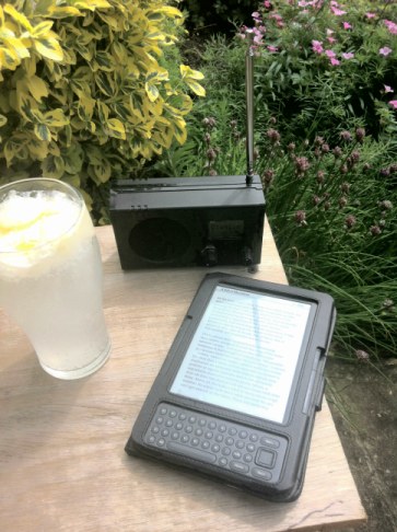
Si4703 FM Radio
Software simplified June 2023
This project was originally designed and built in 2013 when I was relatively new to the Arduino. A few "issues" have become apparent since then:
- I was never happy with the Si4703 'scan' function so I've removed it completely from this version. I've found 14 local
FM stations which I think is enough 'Preset' stations so the scan function isn't really required anyway.
- After some experimenting, it became apparent that the particular Nokia 5110 display I was using seemed to have
a fixed contrast setting. To be consistent with the more usual display, I've replaced it with one that does allow
for the contrast to be adjusted (by holding down the rotary encoder's Push button when turning on the radio) and improved the
sketch to suit. The pinout arrangement is slightly different so I've replaced the ribbon cable connector between the display
and the PCB with short individual "jumper leads".
- The contacts on the rotary encoder started to suffer from more contact bounce with use so I've added a couple of 100nF capacitors across the contacts in this version. To avoid modifying the PCB, I simply soldered the capacitors across the encoder contacts. Contact bounce on the encoder's Push button is more easily compensated for in software so a capacitor isn't required - although it would do no harm to add one.
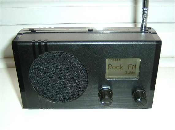
This project is built around the Si4703 FM Tuner Breakout Board from Silicon Labs. It's still available from many suppliers on eBay for around 9 UKP including postage (from China) so represents good value for money.
The Circuit
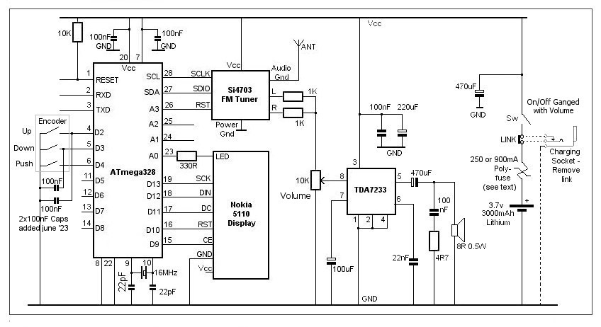
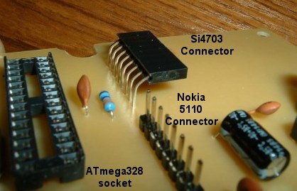
An ATmega328 controls the Si4703 FM Tuner and drives the Nokia 5110 48x84 LCD display.
The ATmega328 RESET, RXD and TXD pins, together with GND, are brought out to pin headers for connecting to the programming hardware. I use a separate RS232-to-TTL converter, such as this one to save having a converter on board.
The two interrupt pins (D2 and D3) connect to a rotary encoder switch for up/down tuning of the Si4703 tuner. (Update June 2023: I added two 100nF capacitors from the encoder contacts to ground to eliminate any contact bounce. I soldered them directly across the encoder contacts to avoid having to modify the PCB.)
Input D4 connects to the push switch on the rotary encoder.
The Nokia 5110 display is driven using ATmega328 pins D9, D10, D11, D12 and D13. The Nokia display is available with several different breakout boards so the pin assignments could be changed if required. I used pin A0 as a digital output to'control' the LED backlight. Some Nokia displays require a GND connection for the backlight; the one I used requires Vcc to turn the backlight on.
The display is connected to the PCB with a short 8-way ribon cable providing additional flexibility in the pin assignments.
I used a display from DX-deal extreme for this project.
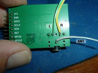
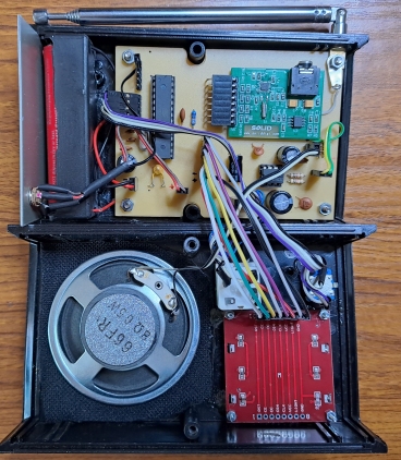
Analogue pins A3, A4 and A5 are assigned to the Si4703 tuner. Audio output from the tuner is normally taken from the 3.5mm stereo socket. In the current design, Left and Right audio channels are picked up from the connections on the back of the tuner breakout board, combined into mono through the two 1K resistors and applied to the 'hot' end of a 10K potentiometer, the slider of which feeds the audio input of a TDA7233 low voltage audio amplifier. Operating at around 3.5 volts, the amplifier provides about 85 mW of audio power into an 8 ohm speaker. The circuitry around the TDA7233 is taken directly from the datasheet.
I've used a 3000mAh Lithium-Ion battery for the power supply. The fully charged voltage (4.2v) doesn't seem to upset the Nokia display and quickly drops to around 3.9 volts anyway. As Lithium batteries can deliver a LOT of current in the event of a fault, I've included a 250mA resettable fuse.
Currently, it's necessary to remove the battery to charge it externally. The intention is to provide a suitable charging socket (with a normally closed contact) on the radio so the PCB provides a removable jumper which will be replaced by a two-pin header plug (connected to the normally closed contact) in order to disconnect the battery from the radio circuitry when it's on charge. Depending on the charger, the polyfuse rating will need increasing. My charger will be around 600mA maximum, so a 900mA polyfuse would be ok. With a trip current around 1.2A, it's still well below the battery's maximum charge/discharge rate.
It may seem unnecessary to disconnect the radio supply during charging but the charger circuit (IC) needs to see the charge current reduce to a pre-set minimum value (10% of the maximum charge current) before it will terminate the charge. With the radio connected, it's possible this lower limit would never be reached so the charger so would never terminate the charge. With Lithium batteries, I prefer to err on the side of caution.
(Lithium charger now completed here.)
PCB Layout
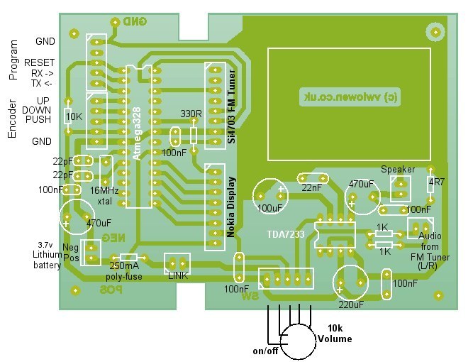

PCB Artwork (Approx actual size)
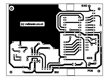
Download Circuit Wizard layout.
Download actual size PDF layout.
Construction
The ATmega328 'sketch'
The software definitely needs improving! It works sufficiently to make a usable radio with 14 preset stations.I couldn't get the 'seek' function to work reliably so I've removed it from this version.
Press and hold the encoder push button while turning the radio on to adjust the display contrast.
Press the encoder push button while the radio is playing to turn the display backlight on for 30 seconds.
Download SparkFunSi4703 Library
Download Adafruit_GFX Library
Download Adafruit_PCD8544 Library
#include <SPI.h>
#include <SparkFunSi4703.h>
#include <Wire.h>
#include <Adafruit_GFX.h>
#include <Adafruit_PCD8544.h>
#include <EEPROM.h>

#define CE 9               // Define pins for the 5110 LCD display.
#define RST 10
#define DC 11
#define DIN 12
#define CLK  13

#define PUSH 4             // Define pin for encoder's Push button.

Adafruit_PCD8544 lcd = Adafruit_PCD8544(CLK, DIN, DC, CE, RST);

int resetPin = A3;         // Define pins for Si4703 FM Radio module.
int SDIO = A4;
int SCLK = A5;

int LED = A0;              // Define pin for LCD backlight.

Si4703_Breakout radio(resetPin, SDIO, SCLK);

byte volume = 7;           // Preset volume for Si4703.  Radio volume is set by 10K potentiomer and TDA7233.


byte presetNumber = 0;
byte oldPresetNumber = 0;

static int encoderUp = 2;    // Rotary encoder 'up' connected to pin 2 (Interrupt 0)
static int encoderDown = 3;  // Rotary encoder 'down' connected to pin 3 (Interrupt 1)

volatile byte aFlag = 0;
volatile byte bFlag = 0;
volatile bool up = false;
volatile bool down = false;
volatile byte raw = 0;

byte contrast = 55;

const int Number_Of_Stations = 14;   // Define number of preset stations.


int fmFreq[Number_Of_Stations] = {989, 889, 915, 937, 958, 967, 971, 974, 1004, 1011, 1059, 971, 911, 1054};
char* fmName[Number_Of_Stations] = {"Radio 1", "Radio 2", "Radio 3", "Radio 4", "Mersey",
                    "City FM", "Buzz", "Rock FM", "Smooth", "Classic ", "Gt Hits", "Capital", "Wales", "Heart"};


long timerLED;

float volts;


void setup() {

  pinMode(RST, OUTPUT);
  pinMode(CE, OUTPUT);
  pinMode(DC, OUTPUT);
  pinMode(DIN, OUTPUT);
  pinMode(CLK, OUTPUT);

  pinMode(LED, OUTPUT);

  pinMode(resetPin, OUTPUT);


  pinMode(encoderUp, INPUT_PULLUP);
  pinMode(encoderDown, INPUT_PULLUP);
  attachInterrupt(0, encoderClockwise, RISING);
  attachInterrupt(1, encoderAntiClockwise, RISING);

  pinMode(PUSH, INPUT_PULLUP);

  contrast = constrain(EEPROM.read(1), 45, 70);
  lcd.begin(contrast);                           // Set LCD contrast from EEPROM

  lcd.clearDisplay();
  lcd.display();

  if (digitalRead(PUSH) == LOW) {               // Hold PUSH down while powering on to
    lcd.setCursor(0, 10);                       // adjust display contrast.
    lcd.print("Set contrast");
    lcd.display();
    delay(100);
    while (digitalRead(PUSH) == LOW);
    while (digitalRead(PUSH) == HIGH) {
      lcd.setCursor(0, 10);
      lcd.display();
      lcd.setContrast(contrast);
      lcd.println("Set contrast");
      lcd.print("Push to save");
      lcd.display();
      if (up) {                                 // Clockwise interrupt (INT 0)
        contrast++;
        up = false;
      }
      if (down) {                               // Anti-clockwise interrupt (INT 1)
        contrast--;
        down = false;
      }
      delay(100);
    }
    EEPROM.update(1, contrast);       // Save new contrast setting (if different from previous)
  }


  presetNumber = constrain(EEPROM.read(0), 0, Number_Of_Stations - 1);

  radio.powerOn();
  radio.setVolume(volume);
  radio.setChannel(fmFreq[presetNumber]);

  oldPresetNumber = presetNumber;

  digitalWrite(LED, LOW);              // Backlight is LOW for 'ON'

  showDisplay();

  timerLED = millis();
}

void loop() {

  if ((presetNumber != oldPresetNumber)) {              // Change in rotary encoder value ?
    radio.setChannel(fmFreq[presetNumber]);
    oldPresetNumber = presetNumber;
    EEPROM.update(0, presetNumber);
    showDisplay();
  }


  if (millis() - timerLED > 30000) {
    digitalWrite(LED, HIGH);                         // Turn Backlight 'OFF' with timer
    timerLED = millis();
  }

  if (digitalRead(PUSH) == LOW) {
    digitalWrite(LED, LOW);                          // Turn backlight 'ON' with PUSH button.
  }
}


void showDisplay() {
  volts = readVcc();
  volts = volts / 1000;

  lcd.clearDisplay();
  lcd.setTextSize(1);
  lcd.print("Preset "); lcd.print(presetNumber + 1);
  lcd.setCursor(0, 16);
  lcd.setTextSize(2);
  lcd.print(fmName[presetNumber]);
  lcd.setCursor(52, 38);
  lcd.setTextSize(1);
  lcd.print(volts);
  lcd.print("v");
  lcd.display();
}


void encoderClockwise() {
  cli();
  raw = PIND & 0xC;
  if(raw == B00001100 && aFlag) {

  if (presetNumber < (Number_Of_Stations - 1)) presetNumber ++;
    bFlag = 0;
    aFlag = 0;
  }
  else if (raw == B00000100) bFlag = 1;
  sei();
  up = true;
  down = false;
}

void encoderAntiClockwise() {
  cli();
  raw = PIND & 0xC;
  if (raw == B00001100 && bFlag) {

    if (presetNumber > 0) presetNumber--;
      bFlag = 0;
      aFlag = 0;
  }
  else if (raw == B00001000) aFlag = 1;
  sei();
  down = true;
  up = false;
}

long readVcc() {
  long result;
  // Read 1.1V reference against AVcc
  ADMUX = _BV(REFS0) | _BV(MUX3) | _BV(MUX2) | _BV(MUX1);
  delay(2); // Wait for Vref to settle
  ADCSRA |= _BV(ADSC); // Convert
  while (bit_is_set(ADCSRA,ADSC));
  result = ADCL;
  result |= ADCH<<8;
  result = 1126400L / result; // Back-calculate AVcc in mV
  return result;
}