The bcd2dec() function works well for the seconds and minutes registers but the hours register is a little different. Only bits 5 and 4 of the high nibble are used to represent the BCD numbers (0000, 0001 and 0010). Here, our bcd2dec function scores over an "off the peg" version because it's easily modified to cater for the "not quite-BCD" Hours register.
byte bcd2dec(byte value, byte mask) {
  byte units = value & B00001111;          // For the units, we only want bits 0 to 3 so mask off the rest.
  byte tens = ((value >> 4) & mask) * 10;  // Shift the top 4 bits to the right, 4 times and mask unwanted bits.
                                           // Then multiply by 10 to make decimal 'tens'.
  return  tens + units;                    // Return the sum.
}
Setting the Time
Reading the time is all well and good but a Real Time Clock isn't very useful without the ability to set the time as well. This is simply a case of writing data to the seconds, minutes and hours registers in much the same way as we wrote data to the Control Register to control the write-protect and the 1Hz LED.Initializing the Control Register makes use of the new writeRegister() function. Note that, unlike the readRegister function, which returns a value, writeRegister() does not return any value but does require two Byte values be sent to it: The address of the register to which we wish to write and the data to put there.
In the case of the minutes register (and the seconds register, if we're going to set the seconds) we need to convert our decimal time values to BCD.... just the reverse of when we read the registers. So, we also need a dec2bcd() function, which we'll use shortly.
The Hours register is slightly different depending on whether we set the 24-hour flag so we send a 'mask' to the dec2bcd() function to mask bits 7 and 6.
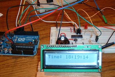
The method used to set the clock depends largely on the finished clock's design. For a data-logger, for example, the simple Serial Monitor shown here would probably do. But a stand-alone clock with, for example, a Liquid Crystal Display, will more than likely have some push buttons to initiate the clock setting process and a method to step a cursor across the display to indicate which digit is being updated.
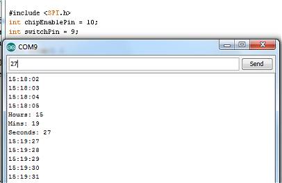
I hooked up the Arduino Digital pin 9 as an input with a 10KΩ pull-down resistor. If this input is taken high, the sketch jumps to the clock-setting functions. The code which initiates the jump is highlighted in green below. The image, below left, shows the Serial Monitor jumping to the setClock() function and responding to the Hours, Minutes and Seconds being entered.
 |  |
#include <SPI.h>
int chipEnablePin = 10;
int switchPin = 9;

void setup() {
  pinMode(chipEnablePin, OUTPUT);
  Serial.begin(9600);
  digitalWrite(chipEnablePin, LOW);
  SPI.begin();
  SPI.setBitOrder(MSBFIRST);
  SPI.setDataMode(SPI_MODE1);   // or SPI_MODE3

  // Initialize RTC Control Register
  writeRegister(0x8f, B00000100); // bit 2 set = 1Hz (pin 7) ON

}

void loop() {

if (digitalRead(switchPin) == HIGH) {
    setClock();
  }

  byte seconds = readRegister(0x00);        // Get the seconds, minutes and hours
  seconds = bcd2dec(seconds, B00001111);    // from the clock's registers.
  byte minutes = readRegister(0x01);
  minutes = bcd2dec(minutes, B00001111);
  byte hours = readRegister(0x02);
  hours = bcd2dec(hours, B00000011);
  if (hours < 10) {
    Serial.print("0");
  }
  Serial.print(hours);
  Serial.print(":");
  if (minutes < 10) {
    Serial.print("0");
  }
  Serial.print(minutes);
  Serial.print(":");
  if (seconds < 10) {
    Serial.print("0");
  }
  Serial.println(seconds);
  delay(1000);
}

byte readRegister(byte Reg) {
  digitalWrite(chipEnablePin, HIGH);
  SPI.transfer(Reg);
  byte getByte = SPI.transfer(Reg);
  digitalWrite(chipEnablePin, LOW);
  return getByte;
}

void writeRegister(byte Reg, byte value) {
  digitalWrite(chipEnablePin, HIGH);         // Enable the Chip Enable by taking it HIGH
  SPI.transfer(Reg);                         // Address the Control Register for a Write.
  SPI.transfer(value);                       // bit 2 set = 1Hz (pin 7) ON
  digitalWrite(chipEnablePin, LOW);          // All done so take the Chip Enable LOW.
}

byte bcd2dec(byte value, byte mask) {
  byte units = value & B00001111;            // For the units, we only want bits 0 to 3 so mask off the rest.
  byte tens = ((value >> 4) & mask) * 10;    // Shift the top 4 bits to the right, 4 times and mask unwanted bits.
                                             // Then multiply by 10 to make decimal 'tens'.
  return  tens + units;                      // Return the sum.
}

byte dec2bcd(byte value, byte mask) {
  byte bcdHigh = ((value / 10) << 4) & mask; // Integer divide by 10 to get the mantissa then shift the result to
                                             // the left most significant bits. mask off unwanted bits.
  byte bcdLow = value % 10;                  // Modulus divide by 10 to get the remainder...
  return bcdHigh | bcdLow;                   // and bitwise OR them to assemble the complete BCD byte.
}


  /* ================================================================================
   * setClock() and getSerialInput() are kludges to test
   * the concept of setting the clock's registers.
   * ================================================================================

void setClock() {
  int val = 0;
  Serial.print("Hours: ");
  val = getSerialInput();
  if (val > 23) val = 0;                     // Check for invalid hours value.
  Serial.println(val);
  val = dec2bcd(val, B00110000);;            // The 'hourx10' BCD nibble only wants bits 4 and 5.
  writeRegister(0x82, val);
  Serial.flush();

  Serial.print("Mins: ");
  val = getSerialInput();
  Serial.println(val);
  val = dec2bcd(val, B11110000);             // The 'minx10' BCD nibble only wants bits 7,6,5 & 4.
  writeRegister(0x81, val);
  Serial.flush();

  Serial.print("Seconds: ");
  val = getSerialInput();
  Serial.println(val);
  val = dec2bcd(val, B11110000);             // The 'secx10' BCD nibble only wants bits 7,6,5 & 4.
  writeRegister(0x80, val);
  Serial.flush();

  while (digitalRead(switchPin) == HIGH);    // Don't return until switch is released.
}


  /* Inputting a character string as a number on the Serial Monitor and returning it to the Arduino
   * isn't straightforward because the Arduino will only accept a byte at a time. This function waits
   * until two characters have been entered on the Serial Monitor, then contructs a 2-digit decimal
   * number and returns it. */


int getSerialInput() {
  int num = 0;
  while (Serial.available() < 2);           // Wait until 2 characters are in the buffer.

  char ch = Serial.read();
  if (ch >= '0' && ch <= '5')               // First character must be between '0' and '5'
    num = (ch - '0') * 10;                  // First character is decimal 'tens'

  ch = Serial.read();
  if (ch >= '0' && ch <= '9')
    num = num + (ch - '0');                 // Add decimal 'units'

  return num;
}