The DS1306 Real Time Clock
Add the code highlighted in yellow and upload the sketch again:
#include <SPI.h>
// The DS1306 CE (chip enable) pin is connected to Arduino digital pin 10.
int chipEnablePin = 10;
void setup() {
// Set the Chip enable pin as OUTPUT.
pinMode(chipEnablePin, OUTPUT);
// The DS1306 datasheet states the chip enable signal must be asserted HIGH
// during a read or a write so set it LOW before the SPI interface is set up.
digitalWrite(chipEnablePin, LOW);
// Set up the Serial Monitor.
Serial.begin(9600);
SPI.begin();
// The DS1306 datasheet states that data is clocked into or out of the registers
// Most Significant Bit first and that it Supports Motorola SPI Modes 1 and 3. We'll use
// Mode 1.
SPI.setBitOrder(MSBFIRST);
SPI.setDataMode(SPI_MODE1); // or SPI_MODE3
// Initialize RTC Control Register
digitalWrite(chipEnablePin, HIGH); // Enable the Chip Enable by taking it HIGH
SPI.transfer(0x8f); // Address the Control Register for a Write.
SPI.transfer(B00000100); // bit 2 set = 1Hz (pin 7) ON
digitalWrite(chipEnablePin, LOW); // All done so take the Chip Enable LOW.
}
void loop() {
digitalWrite(chipEnablePin, HIGH);
SPI.transfer(0x0f); // Address the Control Register but this time for a READ.
byte inByte = SPI.transfer(0x0f); // Read the data into 'inByte' variable.
digitalWrite(chipEnablePin, LOW);
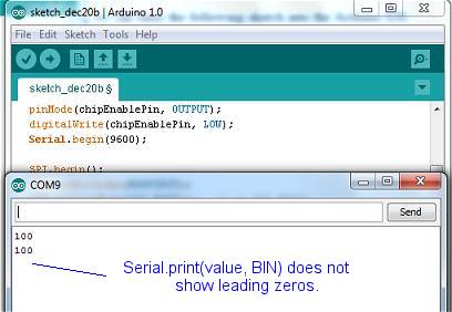
Serial.println(inByte, BIN); // Show the register in Binary on the Arduino Monitor.
delay(5000);
}
Once we've got this far, we can be reasonably sure that both hardware and the SPI communication are working correctly. The next step is to read the Hours, Minutes and Seconds registers, decypher how the data is presented and display it on the Arduino serial monitor.
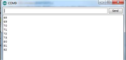
It seems sensible to start with the seconds register since this is obviously changing more rapidly than minutes or hours and will enable us to see if the data read from the register is as we'd expect it to be.
The DS1306 datasheet shows the read address of the seconds register is 00h (0x00) so we can modify the loop() function in the sketch above to show the contents of that register:
void loop() {
  digitalWrite(chipEnablePin, HIGH);     // Enable the Chip Enable by taking it HIGH
  SPI.transfer(0x00);                    // Address the Seconds Register for a READ.
  byte inByte = SPI.transfer(0x00);      // Read the data into 'inByte' variable.
  digitalWrite(chipEnablePin, LOW);

  Serial.println(inByte, DEC);
  delay(1000);
}
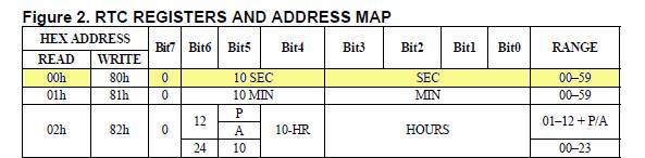
The problem can be seen in the register map (above). The 8-bit seconds register stores the units of seconds in bits 0, 1, 2 and 3 and the tens of seconds in bits 4, 5 and 6. Bit 7 is always '0'.
The value is stored in the register as Binary Coded Decimal - or BCD - so we need to manipulate the 8-bit byte as two separate 4-bit "nibbles". The search term 'Bcd2Dec' appears regularly on the Web but I haven't been able to discover if it's native to Arduino. In any event, it's more useful if we write our own!