The DS1306 Real Time Clock
Some time ago, I had ordered a couple of samples of the Maxim DS1306 Real Time Clock and, as I also had a few 32kHz watch crystals looking for something to do, I decided to try interfacing the DS1306 with my recently-aquired Arduino Uno.I have very little experience with the Arduino system, no experience with the Arduino implementation of SPI and no experience with the DS1306 either so this project should be fun!
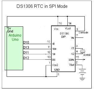
The first step is to build the circuit around the DS1306 on a breadboard. The DS1306 Datasheet shows a typical circuit. You will notice some small but significant changes in the circuit I've used, which is shown below.
The DS1306 can communicate with the full SPI interface using separate Serial Data In and Serial Data Out lines (MOSI and MISO) or with a 3-wire interface by connecting SDI and SDO together (as in the datasheet diagram). The option of using SPI or 3-wire is selected by connecting the SerMode pin to either +5v or Gnd respectively. Although we can use any Arduino digital pin for the DS1306 Chip Enable, the three SPI lines (SCLK, SDI and SDO) are pre-determined by the Arduino SPI Library.
|
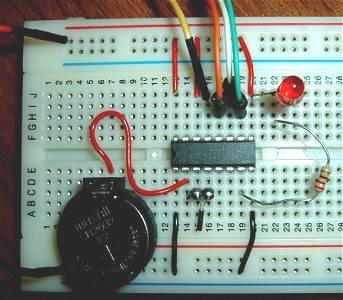
| The 32kHz watch crystal is tiny and won't plug
directly into the breadboard so I soldered it to the top of a two-way female
header. I initially tried a male header but the pins had a tendency to push through the header's plastic when it was inserted into the breadboard. I salvaged the CR2032 Lithium battery and its holder from a defunct computer motherboard. I've also connected an LED between the DS1306 1Hz output (pin 7) and +5v via a 330R resistor. This LED will prove useful to indicate whether the SPI software is set up correctly. This is a low current logic level output not really designed to drive an LED so keep the series resistor as high as possible and use a low current LED. |

 |
Whether the LED will be flashing at 1Hz, or not, depends on the status of a bit (bit 2) in a "Control Register"
inside the DS1306. Other bits in the register control the chip's two Alarm outputs and also determine whether the chip's
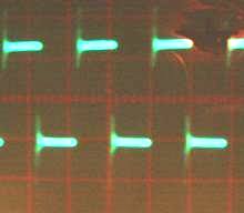
other registers (which contain the time and date) are write-protected. The contents of the Control Register are random when the chip is first powered on so the LED may or may not be blinking. In order to check if the wiring to the chip was sound - before any arduino software was written - I hooked up my ancient oscilloscope to the DS1306 pin 15. If the chip is working and the crystal is oscillating, a 32kHz square wave should be seen at this pin. |
We'll worry about setting the time and date later on; for now we just want to be able to set up the Arduino SPI software. Before we even attempt to read the time and date from the various registers in the DS1306, we should make sure we can write data to the Control Register and successfully read it back again.
As mentioned above, the status of the write-protect bit in the Control register (bit 6) is random at power on so we need to be sure we can set write-protect 'off' before we go any further. We can also set or reset the 1Hz output to our LED (pin 7) by setting bit 2 of the Control Register to '1' or '0'. Once we can successfully turn the blinking LED on or off, we can be sure the SPI interface is working correctly.
With the breadboard hooked up to the Arduino Uno as in the circuit above, we can enter the following sketch into the Arduino IDE:
#include <SPI.h>

     // The DS1306 CE (chip enable) pin is connected to Arduino digital pin 10.
int chipEnablePin = 10;

void setup() {

     // Set the Chip enable pin as OUTPUT.
  pinMode(chipEnablePin, OUTPUT);

     // The DS1306 datasheet states the chip enable signal must be asserted HIGH
     // during a read or a write so set it LOW before the SPI interface is set up.

  digitalWrite(chipEnablePin, LOW);

  SPI.begin();

     // The DS1306 datasheet states that data is clocked into or out of the registers
     // Most Significant Bit first and that it Supports Motorola SPI Modes 1 and 3. We'll use
     // Mode 1.

  SPI.setBitOrder(MSBFIRST);
  SPI.setDataMode(SPI_MODE1);           // or SPI_MODE3

     // Initialize RTC Control Register
  digitalWrite(chipEnablePin, HIGH);    // Enable the DS1306 by taking the Chip Enable pin HIGH
  SPI.transfer(0x8f);                   // Address the Control Register for a Write.
  SPI.transfer(B00000100);              // bit 2 set = 1Hz (pin 7) ON
  digitalWrite(chipEnablePin, LOW);     // All done so take the Chip Enable LOW.
}

void loop() {
     // Do nothing.
}
As with the other registers, the Control Register has two addresses: 0Fh for read operations and 8Fh for write operations. In the sketch above, we only wrote to the Control Register (at address 8Fh). On the next page, we will read the Control Register (at address 0Fh) and display it on the Arduino Serial Monitor to confirm that what we write to the register, we can successfully read back.