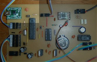
The Real Time Clock
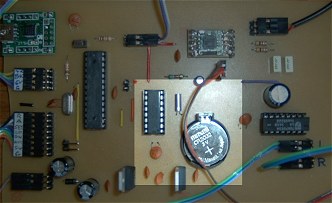 | This photo shows (highlighted) the Real Time Clock section on the final PCB. There's a full section on my site devoted to the DS1360 RTC so I won't repeat it here. The time and alarm setting procedures are a bit more elegant here - see the code section. |
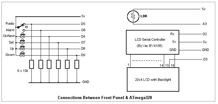
The Front Panel Switches
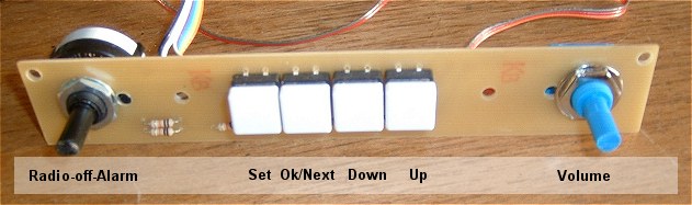
The front panel switches and volume control are fitted to a separate sub-panel which is attached to the front panel itself using stand-off hex pillars. The Radio-off-Alarm rotary switch and the four tactile buttons each have a 10k pull-down resistor to ground.
The panel connects to the main PCB using an 8-way ribbon cable for the switches (plus 5v and Ground) and a three-way cable for the volume control potentiometer. The main PCB end of the ribbon cables terminate in header plugs.
I've provided an additional 2-way header on the main PCB for connecting a second Ok/Next button in parallel with the first. This button simply duplicates the button on the front panel but is situated on top of the case where it's more convenient to use as the "Sleep" and "Snooze" button.
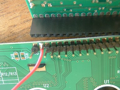
The Liquid Crystal Display
 | 
|
Due to the number of inputs and outputs required by the ATmega328, it wasn't possible to use a simpler parallel-connected LCD.
I like to use a serial controller board from ByVac. Although it's designed to be mounted directly onto the 16-pin header on the LCD itself, I prefer to use a header and socket arrangement.
In any event, in this case, the display and the serial controller need to be ordered separately in order to be able to gain access to the pin on the display board which controls the LED backlight - note the separate flying lead connected to the display pin 15. Pins 1 to 14 and pin 16 connect to the serial controller board as normal.
A light-dependent resistor connected to Arduino analogue pin A3 measures the ambient lighting and controls the Arduino PWM output on digital pin D3 which is connected to the LCD's LED backlight to control its brightness.
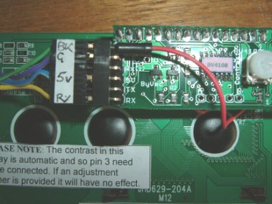
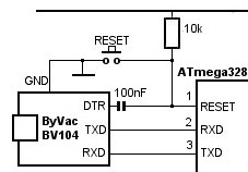
The Programming Hardware
 |
|
This photo shows (highlighted) the programming section on the final PCB.
It's a matter of personal preference whether to include the full-blown USB-to-RS232 hardware, as I have done here, use nothing at all and rely on programming the ATmega328 externally before plugging it into its socket in the alarm clock or to go for something in between!
For example, the USB-RS232 breakout board I used here could be external to the clock, in which case just pins 1, 2 and 3 of the ATmega328 (plus ground and possibly 5v) would need to be accessible......
Very much a case of "you pays your money and takes your choice" ! But, whichever way you do it, the ATmega328 reset pin (pin 1) needs to be pulled to 5 volts through a 10k resistor to prevent it spontaneously resetting itself.