The Radio
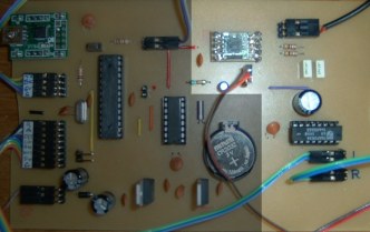 This photo shows (highlighted) the radio section on the final PCB. | 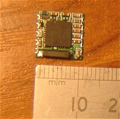
|
Although it would be possible (just) to solder it to the underside of a single-sided PCB, I decided it would be much easier to make a more conventional breakout board complete with 0.1" headers. This simplified the development work on a breadboard and made it easy to solder to the final clock-radio PCB later.
Above (left to right):
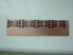
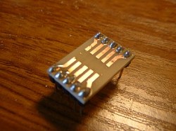
- I etched 4 identical breakout boards by using etch resist transfers. I was then able to choose one with the most accurate alignment.
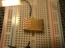
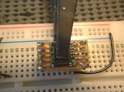
- Although I don't recommend it, I used a breadboard to ensure the pin headers were vertical and aligned with the PCB during soldering.
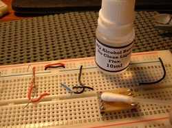
- Breakout board with its two 5-way pin headers.
- As the TEA5767's own breakout board is essentially a surface-mount device, I cleaned my breakout board with an alcohol-based flux to help make sure the solder would flow underneath the TEA5767 pads.
- I held the TEA5767 in position using a spring clamp and soldered the pads using a 1mm soldering iron bit and 0.7mm cored solder.
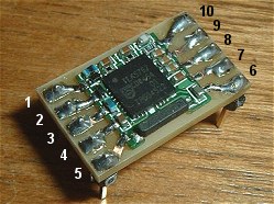
- The finished breakout board. The pin-numbering on the TEA5767 breakout board itself seems to vary depending upon which website you look at so I've shown on the photo the numbering that I've used on my circuit diagram.
The audio output from the TEA5767 is very low and is not enough to drive either headphones or a loudspeaker. The manufacturer's datasheet recommends using a TDA7053 stereo power amplifier (1w per channel). I used a TDA7053A which is very similar except it features a DC volume control which we can exploit in order to mute the audible output. Although it's possible to mute the TEA5767 itself, it risks leaving the audio amplifier with an audible hiss (especially unwanted in a bedside clock!). If you use the TDA5073 instead, bear in mind that the two chips are not pin compatible.

Arduino pin A1 is used as a digital output to supply 5 volts to the TDA7053A's DC volume control on pins 2 and 8. The potential divider formed by the 56k resistor and the 22k potentiometer means there's a maximum of 1.4 volts at the "hot" end of the 22k potentiometer. The TDA7053A datasheet states that any voltage of 1.4 volts and above on pins 2 and 8 results in maximum gain. Taking digital output A1 LOW is used to mute the amplifier. According to the TDA7053A datasheet, any voltage below 0.47v will mute the output.
When the Arduino software detects a match between the actual time and the alarm-time setting, pin A1 is taken HIGH thus un-muting the audio. Arduino pin A2 is used as an analogue input to measure the actual setting of the volume control. If the volume is set too low, Arduino pin A0 (configured as a digital output) will go HIGH sounding a piezo buzzer as well.
Ideally, the input to A2 would measure the actual volume (rather than just the setting of the volume control) but, as the TDA7053A uses balanced speaker outputs (ie neither side of the speaker is connected to ground), it's not sensible to measure the volume this way. Most radio stations - particularly those that would be suitable as a wake-up alarm - tend to have fairly consistently-high volume levels anyway so this shouldn't be a problem.
Also, because neither side of the speaker is grounded, it's not possible to connect the digital output A0 to the speaker so a separate piezo buzzer has to be used.
I provided the TDA7053A with its own 6v power supply. I noticed that the audio tended to distort at higher volume levels when supplied with 5 volts and, in any event, I wanted to keep the potentially noisy Arduino and Real Time Clock supplies separate from the audio amplifier supply. With nearly 40dB of gain, the audio amplifier could be susceptible to picking up noise fairly easily.