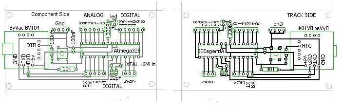
The Printed Circuit Board
One of the most noticable things about modern schematic drawings and printed circuit boards is their complete lack of "personality." I first saw it while at work. There was a time when you could tell who the draughtsman was by simply looking at the "style" of the drawing. But no longer. I suppose that's why I balk at using similar aids at home. I always design my drawings and printed circuit boards using a simple paint program (an old version of Paintshop Pro) so don't rely on the following layout to be exact. As I use rub-on etch-resist transfers, the precise pin-spacing is taken care of when I apply the transfers.Although the Video Switcher only needs three digital pins, it seems sensible to bring all the spare pins on the ATmega328 out to headers for possible future use. If this design proves reasonably successful, I won't need to completely re-design it for the next stand-alone project.
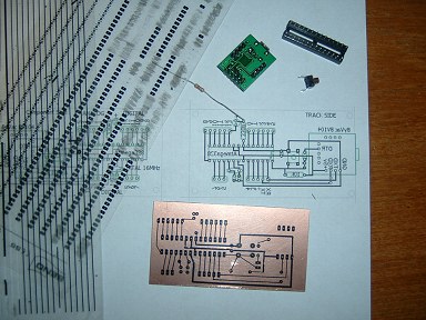 These photos shows the PCB part-way through
applying the etch-resist transfers. | 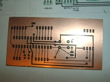 |
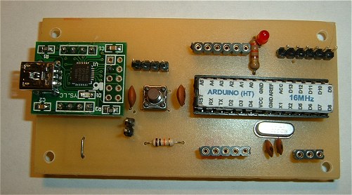
The finished stand-alone Arduino. | 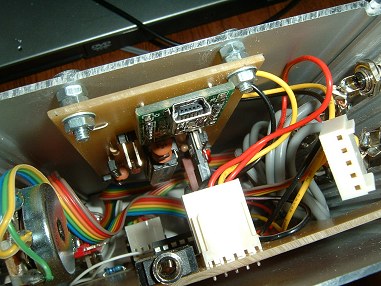
Installed in the Video Switcher. |