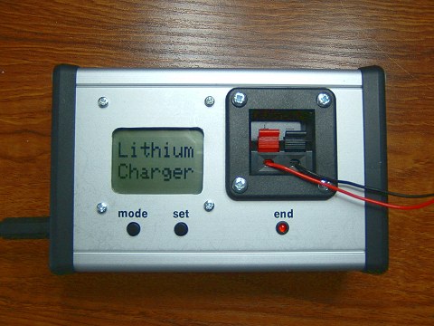
3.6v and 3.7v Lithium Battery Charger
The Circuit
Circuit Description
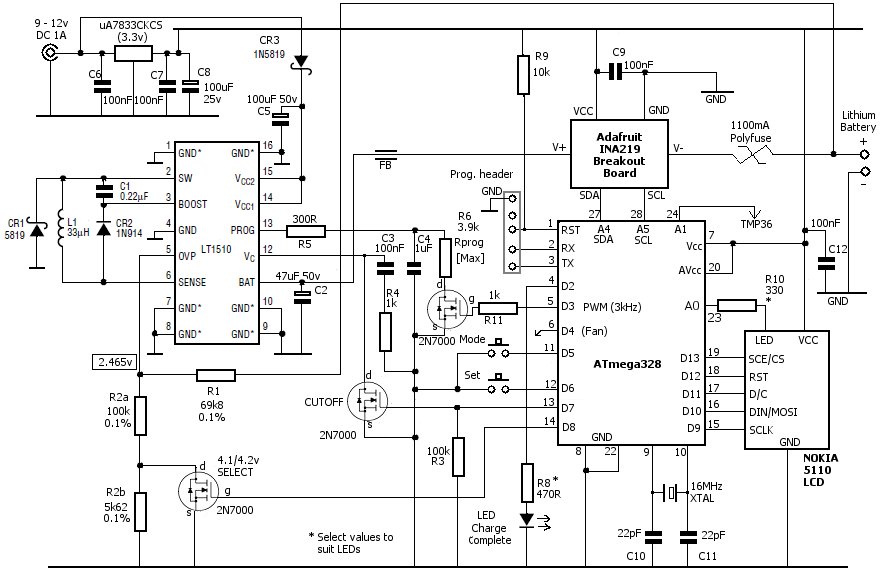
The charger is based on the LT1510IN Constant-Voltage/ Constant-Current battery charger IC from Linear Technology. It can be configured to charge NiCd, NiMH or Lithium-Ion (and Lithium-Polymer) batteries at up to 1.5 Amps.In my circuit, I'm limiting it to 1 Amp maximum to charge 3.6 volt and 3.7 volt lithium batteries only. Charging voltage is critical with lithium batteries and the LT1510 charger IC, controlled with an ATmega328 microcontroller, is able to select a 'target' charge voltage of either 4.1 volts or 4.2 volts, for 3.6 and 3.7 volt batteries respectively.
Lithium battery manufacturers specify that the charge voltage must be correct to within ± 50mV. The LT1510 IC, provides this accuracy by monitoring the voltage at its Over Voltage Protection input on pin 5. The actual output voltage, on its BAT pin, is sampled with the potential divider resistors R1 and R2 (in the circuit diagram), the values of which are chosen to provide exactly 2.465 volts at their junction when the correct voltage is applied to the battery.
Note that the output to the battery passes through an INA219 DC Current Sensor breakout board from Adafruit and a 1.1 Amp resettable 'polyfuse'. The INA219 current sensor works by measuring the volt drop across a 0.1 ohm resistor and the polyfuse itself introduces some additional resistance. Initial polyfuse resistance varies considerably between manufactures and can be anything from around 0.1 ohms to 0.5 ohms or higher. To complicate the use of a polyfuse, its resistance will increase (for several days) once it has been triggered.
Even when the lithium charging current has dropped to, say 100mA, the INA219 and polyfuse could easily introduce a voltage 'loss' in excess of the 50mV specified by the battery manufacturers. From the practical point of view, what this means is that the voltage divider resistors must sample the voltage as close as possible to the battery rather than directly from the LT1510 BAT output pin. The LT1510 is then able to adjust the voltage from its BAT pin until it sees the required 2.465 volts on its OVP pin. In this way, the LT1510 maintains the accuracy of the voltage across the battery to within ± 1 or 2mV.
Unlike the LT1510, the INA219 current sensor has no option but to read the battery voltage on the "wrong" side of the polyfuse. Luckily, as the current is known and the initial resistance of the polyfuse can be measured (or estimated), the ATmega328 software is able to compensate for the volt drop across the fuse before displaying the voltage on the Nokia 5110 display. Even so, the voltage shown on the display should be regarded more as a guide (say, ±10mV) rather than as an absolutely accurate voltage measurement.
Note that, due to the design of the LT1510, if no battery is present when power is applied, the voltage on the BAT pin will rise to near the supply voltage. Although the available current is clamped at zero until the charging parameters have been set up with the ATmega328, it's recommended to connect the battery to be charged before applying the external DC power.
Switching Between 4.1 and 4.2 volts
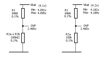
In order to supply either 4.1 volts or 4.2 volts to the battery yet still achieve exactly 2.465 volts at the R1/R2 junction, R2 is actually two resistors in series, one of which can be switched out.
When an output of 4.1 volts is required, the sum of R2a and R2b (105.62k ohms) is used. Allowing for the tolerances of the specified 0.1% resistors, the lowest battery voltage that will achieve 2.465 volts at the R1/R2 junction is 4.091 volts and the highest is 4.095 volts. Well within the specified ±50mV tolerance but erring on the low side for battery safety and longevity.
When a 4.2 volt charging voltage is required, ATmega328 output D8 turns on the 2N7000 MOSFET, which shorts R2b to ground.
The potential divider now consists of just R1/R2a. With the resistor tolerances specified, the lowest output voltage (to achieve 2.465 volts at the R1/R2 junction) is
now 4.182 volts and the highest is 4.189 volts. Again, nicely within the ±50mV tolerance and erring on the low side.
Setting the Charging Current
A Lithium battery begins charging with a constant current until its voltage rises to near the set charging voltage (4.1 or 4.2 volts). The current then gradually reduces naturally as the battery charge increases. With the LT1510, the initial constant charging current is determined by a programming resistor connected between its PROG pin and ground (R5 + R6).Using a 300 ohm resistor in series with a 3k8 resistor provides a maximum charge current of 1.170 Amps.
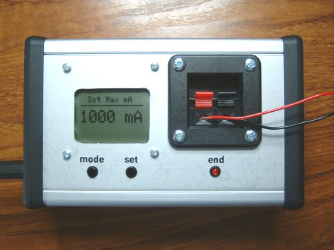
However, by connecting the programming resistor to ground through a 2N7000 MOSFET and using the ATmega328 to apply pulse width modulation (PWM) to its gate, it's possible to set any initial charging current (up to the limit set by the resistor). The Arduino Sketch allows an initial charging current of 100mA, 250mA, 500mA, 750mA or 1000mA to be set but any other values could be chosen by changing the PWM values in the Sketch.
Capacitor C4 and resistor R5 are used to average the output of the constant-current loop. The LT1510 application note (design manual) shows a MOSFET connected with PWM in its figure 21.
The LT1510 datasheet recommends a minimum PWM frequency "higher than a few kHz". The default ATmega328/Arduino PWM frequency is only 500Hz so the Arduino sketch changes the ATmega328 PWM frequency on pin D3 to around 3.9kHz. (Actually, pin D11 frequency is changed as well but this doesn't affect the operation of the Nokia 5110 LCD display which uses pin D11 in its 'normal' digitalWrite mode).
Setting the Terminating Current
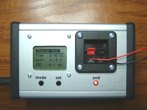
As the lithium battery approaches full-charge, the current automatically reduces. The LT1510 allows the battery to stay connected indefinitely when the current is near zero but other lithium charger ICs I've used terminate the charge when the current drops to 10% of the initial charging current. Lithium battery manufacturers don't normally recommend leaving them connected on a 'float' charge.Because the ATmega328 is constantly monitoring the current (as seen by the INA219 breakout board), it can pull the Vc pin on the LT1510 to ground through another 2N7000 MOSFET when it sees a suitably low current, which immediately terminates the charge. Additionally, of course, the PWM output to the programming resistor MOSFET can reduce the charging current to zero.
The choice of the terminating current for lithium batteries seems to be somewhat arbitrary: The Battery University website suggests the cutoff should be at 3% of the battery's rated current. The MCP73837 Lithium Charger IC sets the limit internally at 10% of the initial charging current.
As this is under the ATmega328 software control in our circuit, it will be simple to tweak the terminating conditions - perhaps extending the charge time by a few minutes after the 10% value is reached or reducing the set point to, say, 5%. As presented here (on page 3), I've set the cutoff at 10%.
The Power Supply
The LT1510 is a switching/buck type regulator and can operate over a large range of input voltages. The datasheet specifies a minimum input voltage (on its Vcc pins) of 7 volts DC. There's approximately 0.3 volts dropped across the 1N5819 Schottky blocking diode so the minimum external power supply is nearer 8 volts. The LT1510 maximum input voltage is claimed to be up to 28 volts DC.The ATmega328, the INA219 and the Nokia 5110 display operate at 3.3 volts so the circuit includes a simple 3.3 volt regulator using a uA7833CKCS 500mA regulator. Some Nokia 5110 displays will run at 5 volts but, as 5 volts is at the top of its maximum limits, I prefer to run them at 3.3 volts. C8 provides the usual DC smoothing to compensate for an 'unknown' external power supply and C6 & C7 100nF capacitors provide high-frequency noise suppression, the electrolytic capacitor, C8, being ineffective at high frequencies.
With an external power supply no higher that 13.8 volts, the uA7833CKCS doesn't require a heatsink but the 12 volt cooling fan limits the maximum input to 12 volts.
The uA7833CKCS is 'unusual' for a 3.3v regulator in that it's pin-compatible with a standard LM7805. If you want to run the ATmega328, the INA219 and the Nokia 5110 display at 5 volts, the PCB layout shown on the next page will accomodate an LM7805 without modification.
Thermal Considerations
Like all power-producing electronic components, lithium charger ICs need to be adequately heatsinked in order to get anywhere near their rated output current. Unfortunately, most lithium charger ICs also seem to be surface mounted devices (SMDs). Some are managable (just) but others are so small they seem to have entered the realm of quantum physics - approach them with the soldering iron and they instantly seem to move to a new location!In any event, to obtain adequate heatsinking these SMDs need at least a double-sided PCB (with the top side ground plane acting as the heatsink). And, to obtain, reasonable soldering capability, SMDs need a PCB covered with solder-mask.
Both of these requirements put me off SMD devices so I was pleased to find that the LT1510 is available in a standard 16-pin DIP package as types: LT1510CN, LT1510CN#BPF, LT1510IN and LT1510IN#BPF. See the Ordering Info at the Linear Technology Website for details. The bad news is that none of the usual suppliers stock the DIP version. The good news is that they're available directly from Linear Technology. Even better, they seem happy to supply a limited quantity (2) of free samples - even to us hobbyists.
The thermal capabilities of the DIP version isn't quite as good as its SMD versions (75°C/W and 50°C/W respectively) but I believe the convenience of the DIP package, using simple PCB-manufacturing techniques, and the ability to easily attach external heatsinking to both the IC and the PCB, outweighs the slight thermal disadvantage!
Cooling Fan
With a charging current below about 450mA, the temperature of a small heatsink attached to the LT1510 barely rises above ambient. Between approximately 450mA and 650mA, the temperature stablises at around 27°C. Higher than 650mA, however, the temperature rises fairly rapidly to 30°C and beyond.For this reason, I fitted a small (25x25mm) fan to one end of the case (and the corresponding air vent holes in the opposite end).
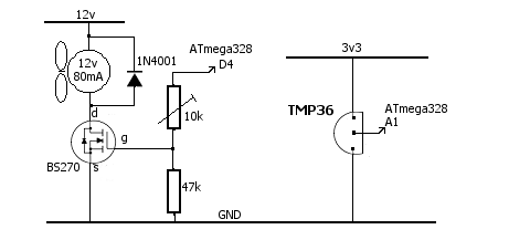
The fan was quite noisy so I fitted a 10k preset to vary the voltage on the MOSFET gate, hence the fan speed. As the MOSFET isn't being switched fully on, I used a BS270 MOSFET which has slighly better power handling than the 2N7000. Even so, the BS270 still runs slightly warm.
A simpler alternative would be to wire a suitable 1/2 watt resistor in series with the 12v fan supply and dispense with the 10k potentiometer altogether. Around 220R 1/2 watt should be suitable but, as the exact value depends on the particular fan, I decided to use the potentiometer instead.
Whichever method is used, ensure the fan starts reliably when it's running at the reduced speed.
I did try to use a PWM output from the ATmega328 but the brushless fan motor didn't seem to want to co-operate at all!
Initially, I controlled the fan simply by switching on ATmega328 output D4 whenever the current was above 500mA but decided to control it by temperature using a TMP36 temperature sensor superglued to the LT1510 heatsink and connecting its analogue output to the ATmega328 analogue input A1. The software switches on the fan whenever the heatsink temperature rises above 30°C and switches it off once the temperature drops below 28°C.