This project uses potentially lethal mains voltages and comparatively high currents. Do NOT skimp on safety arrangements such as earthing (grounding), fuses, ventilation and preventing access to live parts through ventilation slots.
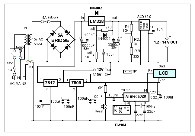
The variable voltage regulator circuit is based on the examples provided in the National Semiconductor LM338 datasheet. The value of the smoothing capacitor on the input side is a compromise between minimizing the ripple voltage on one hand and physical size/cost considerations on the other hand.
The ripple voltage is a function of the output current, the supply frequency and the value of the smoothing capacitor. Here in the UK, with a supply frequency of 50Hz, the ripple voltage can be calculated using the formula:
                       10 x (Load Current in mA)
          Vr (volts) = -------------------------
                               C (uF)
If we calculate for the worst case (ie 3 Amps), the ripple volatge works out as 3 volts - which, at first sight
seems very high. However, the LM338 has good ripple rejection which is improved further with the 10uF capacitor connected across
the 5k multi-turn voltage adjustment variable resistor. The 3,300uF capacitor on the output should help reduce the ripple even
further.In practice, the ripple voltage is undetectable on my old oscilloscope (Y-amplifier set to 5mV/Div) with a 2 amp load at 12 volts.
The regulation is better than I had expected: With the output set at 15.3 volts into a 2.2 amp load, the voltage rises to 15.5 volts when the load is removed. At 5.00 volts, 1.14 amps, the voltage rises to 5.01 volts at zero amps.
Monitoring the Voltage and Current
The above more or less completes the description of the actual variable power supply. The rest of the circuit is for measuring the output voltage and the current being taken by the external load.For this purpose, I've used two analogue input pins on an ATmega328 microcontroller. The microcontroller then sends the values of voltage and current to an LCD display mounted on the power supply's front panel.
Voltage Measurement
Resistors R1, R2a and R2b form a potential divider across the power supply output. With the values shown, the voltage at the junction between R1 and R2a is given by:
                   Vin x (R2a + R2b)
          Vout =   -----------------
                    R1 + R2a + R2b


                     Vin x 3,330
               =   ---------------
                    10,000 + 3,330

      at 20 volts in:

                   66,600
          Vout =   ------
                   13,330

          Vout =   4.99 volts.
The analogue input pin on the microcontroller produces a digital value in the range 0 to 1023 as the volatge on the pin varies
between 0 and 5 volts. Therefore, the digital value is directly proportional to a maximum power supply output voltage of 20 volts.
Small errors due to variations in the actual resistors' values will be adjusted in the ATmega328 program. The important point is
to select resistor values which ensure that a maximum of 5 volts is available at the R1-R2 junction when the LM338 voltage
regulator is set to maximum output with no load.
It's worth measuring the actual resistance values (with an ohmmeter) before you solder them to the PCB. Make a note of the values because they can be inserted into the ATmega328 program later to increase the accuracy of the value displayed on the LCD.
Current Measurement
The most common method of measuring current is to insert a low-value, high-wattage resistor in series with the output and measuring the voltage drop across it. By simple Ohm's law, the current can be calculated. For example, using a 0.01 ohm resistor, 4 Amps passing through it would result in:
        V = Amps x Resistance

          = 4 x 0.01

          = 40 mVolts
As the range of the microcontroller's analogue input is 0 to 5 Volts, the voltage dropped across the resistor is too small to give
good resolution so a x10 or even x100 amplifier needs to be used.Although I had some useful results with an AD623AN Instrumentation Amplifie set to a gain of 10, a high gain amplifier is sensitive to external noise so its use here may not be ideal. Increasing the value of the "shunt" resistor would increase the available volt drop but at the expense of increasing its power dissipation and reducing the maximum available output voltage.
There's an interesting article about making low ohmic value shunts here if you want to try that method.
The ACS712 - 5A Current Sensor
As an alternative approach, the Allegro MicroSystems ACS712 is a Hall Effect device especially designed for exactly our requirements. Although it's a Surface Mount Device, Sparkfun Electronics manufacture a breakout board and it's available in the UK from HobbyTronics.co.uk.The 5 Amp version produces 185mV / Amp so, at 4 Amps, we can expect 740 mV. This is about twice the resolution we'd get from a 0.01 Ω resistor with a x10 amplifier and should provide around 0.05 amps resolution for the microcontroller input which, I think, is more than enough for our requirements.
The sensor can actually measure up to 5 amps in either direction so it has an output "centre point" of 2.5 volts. That is, with zero current, the output will be 2.5 volts and will increase at the rate of 185mV/A with the current flowing in one direction and will decrease at 185mV/A when it flows in the other direction. Of course, in our project, the current will always flow in one direction but it does mean that we don't need to worry about which way round we need to connect it because we simply adjust the ATmega328 program to suit.
Additional Voltage Outputs
The ATmega328 microcontroller needs a stable 5 volt supply which is obtained from a standard 7805 1A regulator. As the processor only uses a few milliamps, the 5 volts supply is available as an additional fixed output from the power supply.As the DC voltage from the bridge rectifier is around 20 volts off load, this is too high to feed directly to the 7805 without it needing a huge heatsink. Therefore, the output from the bridge rectifier is first fed to a 7812 12 volt 1A regulator. Again, this volatge is also available as a fixed output from the power supply.
Both of these regulators only have small heatsinks so their outputs are really only good for a few hundred milliamps or so before they start to protect themselves by limiting the available current - but there's enough current for most elecronics uses.
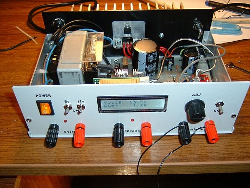
The LCD Display & USB-Serial
I used a 2 rows x 16 characters LCD display complete with a serial board from ByVac Electronics. Displays without the serial controller are also available - there are plenty of spare output pins available on the ATmega328 if you don't mind the extra bit of work wiring up a parallel LCD display.The software presented later (on Page 5) assumes the use of the BV4108 (IASI-II) serial controller.
The BV104 (also from ByVac Electronics) is a USB-to-Serial converter used to program the ATmega328. It's a bit of a luxury; instead of permanently soldering in the BV104, it could be plugged into a female header when required - or the ATmega328 could just as easily be programmed using an Arduino - but I included it for completeness (I had one spare which had been unsoldered from another project and its connection pins were no longer "clean" enough to plug into a female header socket.).
Note the 'DTR' connection from the BV104. This is used to provide an automatic reset to the ATmega328 during programming. It's available on the 'RS232' connection pads on the BV104 (not on the main 2x4 way terminal pins) so you need to connect it separately with a short link of wire... the pad on the PCB layout shown on the next page should be directly below the DTR pad on the BV104.
If you decide to use a temporary 'plug in' arangement for the BV104, bear in mind that you'll need to make provision for connecting the DTR signal -- alternatively, you can use the Reset button on the power supply's PCB instead of the automatic-reset from the DTR signal.