November 2014
Programming the ATtiny84
The ATtiny84 is programmed using the Arduino environment with either an Arduino Uno or a dedicated programmer.It's necessary to define the ATtiny84 core so the Arduino IDE knows about its pins. Be aware there are a couple of different libraries for the ATtiny84 that treat the ATting84's internal registers differently.
The library I used is arduino-tiny. The 'README' included in the downloaded zip package contains full instructions for installing it into the Arduino IDE.
There are dozens of websites detailing how to use the Arduino Uno as a programmer - particularly for the ATtiny84 - so I won't repeat them in detail here.
In brief, the steps are:
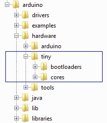
- Download the arduino-tiny library (arduino-tiny) and, with the
Arduino IDE closed, extract the files
to the main Arduino hardware folder. Something like:
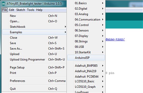
- Open the Arduino IDE and open ArduinoISP from the Examples folder. Make sure the Arduino Uno is
selected in Tools | Boards and upload the ArduinoISP sketch to the Uno in the usual way:
- Power down the Uno and connect it to the ATtiny84 as follows:
Arduino - ATtiny84 (Uno pin designations) (actual IC pin numbers) 5v - Pin 1 GND - Pin 14 D13 - Pin 9 (SCK) D12 - Pin 8 (MISO) D11 - Pin 7 (MOSI) D10 - Pin 4 (Reset) - When the Arduino Uno is acting as a programmer, it's necessary to disable its auto-reset circuit. To do this,
connect a 10uF capacitor between RESET and GND on the Arduino Uno board (Capacitor negative to GND). The capacitor 'absorbs' the auto-reset pulse from the USB/serial and prevents the Uno's ATmega328 seeing it.
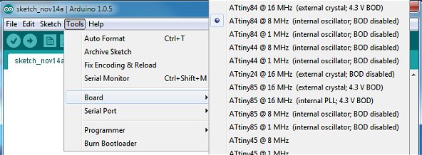
- From the Arduino Tools | Board menu, select the ATtiny84 chip: ATtiny84 @ 8 MHz (internal oscillator; BOD disabled):
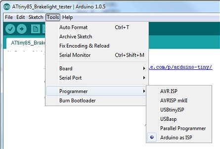
- From the Arduino Tools menu, select Programmer | Arduino as ISP.
- Power up the Arduino Uno (with the USB cable), ensure the correct COM port is still selected and, from the Tools
menu, select Burn Bootloader. This doesn't actually burn a bootloader in the ATtiny84 but it does set the internal
fuses to match the board type we selected in step 5.
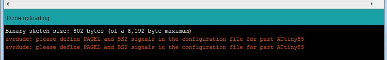
- Finally, load the MP3 Player Sketch into the Arduino IDE and hit Upload in the usual way. You
will see the errors shown below. They only apply if you're using an external parallel programmer so it's safe to
ignore them. The ATtiny84 should now be successfully programmed with the MP3 Player sketch.
The Arduino Sketch
// MP3 Module from http://www.embeddedadventures.com/soundout_mp3_module_mod-1021.html
// Player software & supporting hardware (c) 2014 vwlowen.co.uk


#include <SoftwareSerial.h>
#include <EEPROM.h>

#define rxPin 1                             // Software Serial Rx from MP3 Module Tx pin.
#define txPin 0                             // Software Serial Tx to MP3 Module Rx pin.

// Define the MP3 Module's Commands that we'll be using
#define cmdNextTrack  0x01                  // Next track.
#define cmdPrevTrack  0x02                  // Previous track.
#define cmdRepeatPlay 0x11                  // Repeat play.

#define cmdSetVolume  0x06                  // Set Volume to a specified value.
#define cmdSetEq      0x07                  // Set Equalizer to a specified value.
#define cmdReset      0x0c                  // Reset MP3 Module.

int savedVolume = 0;                        // EEPROM locations for saving current volume
int savedEq = 2;                            // and equalizer values.

boolean changed = true;                     // Don't write EEPROM if value hasn't changed.

int pinRepeatPlay = 8;                      // Define pins for 5-way navigation switch.
int pinVolDown =  5;
int pinVolUp = 6;
int pinPrev = 9;
int pinNext =  7;
int pinEq =  10;                            // Equalizer select button.


 int pinLED = 2;                            // Busy LED for ATTiny84;
int pinBusy = 3;                            // Busy signal from MP3 module.

SoftwareSerial mp3(rxPin, txPin);           // Create software serial for MP3 module.

unsigned int volume = 10;                   // Starting MP3 module volume (0 - 31).
unsigned int eq = 0;                        // Normal/Pop/Rock/Jazz/Classic/Base equalizer.

// Initialize send buffer for MP3 module command string.
byte cmdBuff[10] = {0x7e,                   // Start Byte, always 0x7e.
                    0xff,                   // Version, always 0xff.
                    0x06,                   // Data length, always 0x06 for us.
                    0x00,                   // Command value.
                    0x00,                   // Feedback, always 0x00 ('No feedback') for us.
                    0x00,                   // Command parameter Hi Byte.
                    0x00,                   // Command paramemer Lo Byte.
                    0x00,                   // Checksum Hi Byte.
                    0x00,                   // Checksum Lo Byte.
                    0xef                    // End Byte, always 0xef.
                    };


void setup() {
  pinMode(pinRepeatPlay, INPUT_PULLUP);             // Set button pins as inputs and
                                                    // enable internal pullups.
  pinMode(pinVolDown, INPUT_PULLUP);
  pinMode(pinVolUp, INPUT_PULLUP);
  pinMode(pinEq, INPUT_PULLUP);
  pinMode(pinPrev, INPUT_PULLUP);
  pinMode(pinNext, INPUT_PULLUP);

  pinMode(pinBusy, INPUT);                      // Input from MP3 module. No pullup needed.
  pinMode(pinLED, OUTPUT);                      // Busy LED.  Echo the module Busy signal.

   mp3.begin(9600);                              // Initialise software serial.
  delay(150);
  sendCommand(cmdReset, 1);                     // Reset MP3 module (command, parameter).


  // Get last volume & equalizer values from EEPROM. Values will be wrong the very first
  // time power is applied so keep them within sane limits.

  volume = EEPROM.read(savedVolume);            // Only read Lo byte. Hi byte is always 0x00.
  if (volume > 31) volume = 10;
  eq = constrain(EEPROM.read(savedEq), 0, 5);   // Only read Lo byte. Hi byte is always 0x00.

  digitalWrite(pinLED, HIGH);             // MP3 module busy signal is active low.

}


// Routine to build 10-byte command buffer and write to software serial Tx (MP3 module Rx).
void sendCommand(byte Cmd, unsigned int Param) {
  unsigned int sum = 0;

  cmdBuff[3] = Cmd;                    // Command.
  cmdBuff[5] = (byte) (Param >> 8);    // Param Hi byte.
  cmdBuff[6] = (byte) (Param);         // Param Lo byte.

  for (int i=1; i<7; i++) {            // Calculate 16-bit checksum from buffer bytes 1 to 6.
    sum -= cmdBuff[i];
  }

  cmdBuff[7] = (byte) (sum >> 8);      // Add checksum Hi byte to buffer.
  cmdBuff[8] = (byte) sum;             // Add checksum Lo byte to buffer.

  for (int i = 0; i<10; i++) {         // Write entire buffer to software serial (mp3).
    mp3.write(cmdBuff[i]);
  }
}

void restoreSaved() {
  sendCommand(cmdSetVolume, volume);                       // Set last volume.
  delay(100);
  sendCommand(cmdSetEq, eq);                               // Set last equalizer vaule.
  delay(100);
}


// Loop through checking for a button-presses.
void loop() {

  if (digitalRead(pinRepeatPlay) == LOW) {               // Start repeat-play.
    restoreSaved();                                     // Tell the MP3 module Vol and Eq values.
    sendCommand(cmdRepeatPlay, 1);                       // Send Repeat-Play command to module.
    while (digitalRead(pinRepeatPlay) == LOW);
    delay(150);
  }

  if (digitalRead(pinVolDown) == LOW) {                    // Volume down button
    if (volume > 0) volume--;
    sendCommand(cmdSetVolume, volume);                     // Send volume command.
    changed = true;                                        // Flag that value has changed for EEPROM
    delay(150);
  }

  if (digitalRead(pinVolUp) == LOW) {                      // Volume Up button
    if (volume < 31) volume++;
    sendCommand(cmdSetVolume, volume);
    changed = true;
    delay(150);
  }

  if (digitalRead(pinEq) == LOW) {                         // Equalizer button
    eq++;
    if (eq > 5) eq = 0;                                    // 0 -> 5 -> 0
    sendCommand(cmdSetEq, eq);                             // Normal/Pop/Rock/Jazz/Classic/Base
    while(digitalRead(pinEq) == LOW);
    changed = true;
    delay(150);
  }

  if (digitalRead(pinPrev) == LOW) {                       // Previous Track button
    restoreSaved();
    sendCommand(cmdPrevTrack, 0);
    while(digitalRead(pinPrev) == LOW);
    delay(150);
  }

  if (digitalRead(pinNext) == LOW) {                       // Next Track button
    restoreSaved();
    sendCommand(cmdNextTrack, 0);
    while(digitalRead(pinNext) == LOW);
    delay(150);
  }

   if (changed) {                                           // If a value has changed write to EEPROM
    EEPROM.write(savedVolume, volume);                     // Volume
    EEPROM.write(savedEq, eq);                             // Equalizer setting.
    changed = false;
  }
}