The Mood LEDs
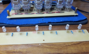
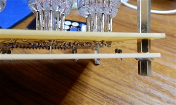
There's not much that can be said about the mood LEDs! Six slow-colour-changing LEDs with their associated 330R resistors mounted on a PCB. The PCB is mounted on hex spacers below the main PCB with the LEDs pushed through 6mm holes in the main PCB and soldered such that the top of each LED is close to, but not touching, the base of its IV-12 tube.
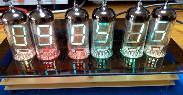
These six LEDs naturally produce a random (unsynchronised) change of colours which I think looks quite good. I fitted them on their own PCB rather than trying to incorporate them into the main PCB to allow for some flexibility should I want to change them in the future. Although there isn't much space below the main PCB, there would be enough for surface mounted components such as a separate micro-processor.
The Enclosure
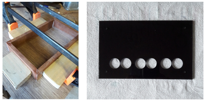
The enclosure was made from spare wood I found in the garage, glued together with mitred joints and clamped in a cobbled-together frame while the glue dried. I made the inside measurements exactly the same as the main PCB so there is no sideways movement when the PCB is dropped in from the top. The holes for the tubes in the acrylic sheet were cut with a 22mm cutter after first drilling 3mm pilot holes.
I printed out a spare copy of the PCB artwork on plain paper and used that as a template to mark out and drill the holes in the acrylic sheet.
Note that the datasheet for the IV-12 tubes shows a diameter of 22.5mm however, mine were only 21.5mm.
The Remote
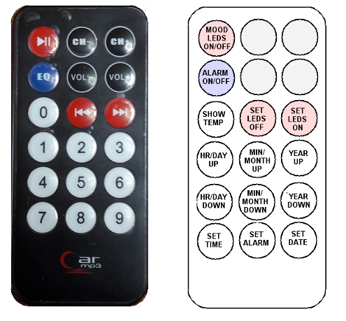 I used a cheap remote that originally came with a portable MP3 player. The Arduino program and the TSOP38238 IR receiver are compatible with most
remotes.
I used a cheap remote that originally came with a portable MP3 player. The Arduino program and the TSOP38238 IR receiver are compatible with most
remotes. Once the Arduino program (sketch) shown on the next page has been uploaded to the ATmega328P, you can check the codes that your remote issues on the Arduino Serial Monitor. Copy the codes into the #define lines in the sketch.
Keys on cheap remotes are unlikely to be marked with labels that suit our needs so it's a bit of a memory test as to which key does what! This photo shows my remote and the function I assigned to each key.
The Arduino sketch automatically reverts to displaying the time if no key is pressed after 5 seconds but this value is easily changed in the sketch.
Pressing any SET key will enter 'edit' mode:
SET LEDS OFF and SET LEDS ON enters the edit mode for switching the mood LEDs off and on. When in edit mode, use the HR/DAY UP key to increment the hours, MIN/MONTH UP to increment the minutes and so on.
The Mood LEDs ON and OFF times only become active if they are different. Set the same time for both if you don't want timed switching.