Lithium-Ion, Lithium-Polymer Charger
In any event, I decided, it would be more versatile to build a separate charger with two or three charging current options. Virtually all lithium charger ICs are tiny Surface Mount Devices (SMDs) - the few that are available in a DIP package have a high external component count increasing the complexity. In fact, some use so many external components, it would seem more sensible to dispense with the IC altogether!
The MCP73837
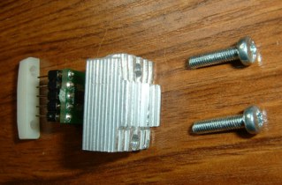
I decided to use the MCP73837 from Microchip. It has a programmable maximum charge current (up to 1A) and has a dual power supply capability - USB or a DC Power Adaptor.Unfortunately, the MCP73837 comes in a tiny MSOP-10 package - too small for me to work with these days. I use a company called Tirna Electronics who supply SMD to DIL breakout boards (adapters) and they're able to source the IC from either RS Compoents or Farnell and solder it to the breakout board.
The Circuit
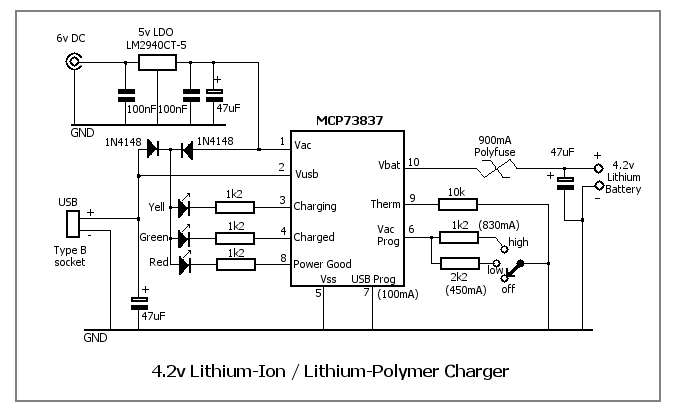
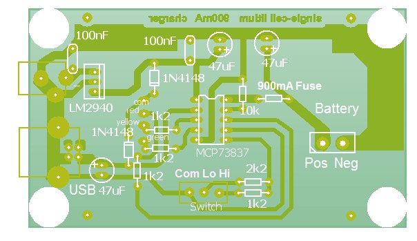
The circuit is taken straight from the MCP73837 datasheet except for the addition of the 900mA resettable fuse and the switched programming resistors connected to Vac prog.
Note that the IC pin designations Vac (Pin 1 on the IC) and Vac prog (Pin 6 on the IC) are from the datasheet. References to 'ac' are a bit confusing. They refer to the use of an AC-DC 'Wallmart' type adapter for the power supply - the power to Pin 1 must be DC.
I used a 5v LDO regulator to provide 5 volts DC to the IC. 6v DC is the maximum input to the LDO due to the limited size of the heatsink on the LDO.
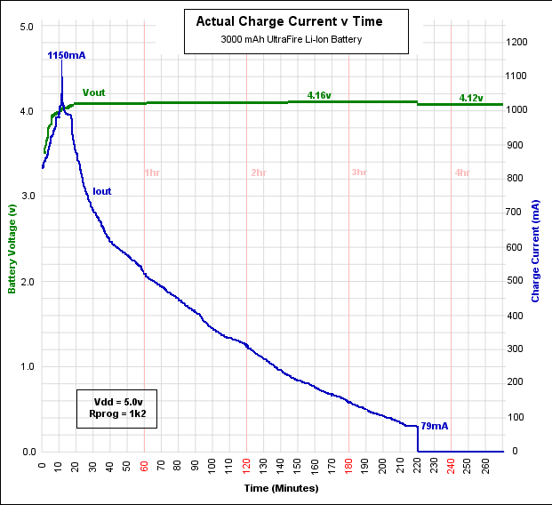
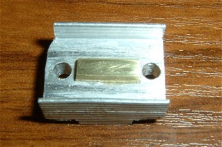
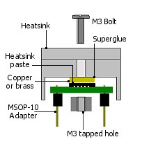
Because I've used an MSOP breakout board for the MCP73837, it's not possible to use the main printed circuit board copper ground plane as a heatsink. Although I've cobbled together a heatsink, of sorts, I decided to restrict the HIGH charge current to around 830mA. The LOW setting provides 450mA charge current. The charge current is set using switch-selectable resistors connected betweem Vac prog and ground.
When using the USB power source, the charge current is limited to 100mA regardless of the switch setting. In practice, the USB ports on my computer only provide around 90mA maximum.
If both DC power (Vac) and USB power (Vusb) are connected at the same time, the MCP73837 automatically uses Vac as the power source and the maximum charge current is determined by the setting of the HIGH/LOW switch.
Regardless of which power source is in use, making Vac prog open circuit (HIGH/LOW setting to OFF) will terminate the charge and put the charger into standby.
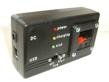
Three LEDs indicate 'Power Good', 'Charging' and 'Charged'. If you use different coloured LEDs, you may need to tweak the values of the LED series resistors if you're fussy about having the LEDs equal brightness.
I'm regarding this version of the charger as a 'Mark 1'. The case I chose was a bit too shallow to allow for a decent heatsink on the 5 volt LDO regulator. As a result, the input voltage has to be kept to 6v (I was hoping for 6 - 9v) and, even at 6v, the LDO gets quite hot during the initial charge. A 1.5A regulator would probably help. A larger case may allow for some additional functionality as well.
The Printed Circuit Board
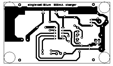
Above: PCB copper side. Actual size.
Below: PCB layout. Component side.
The MCP73837 Heatsink
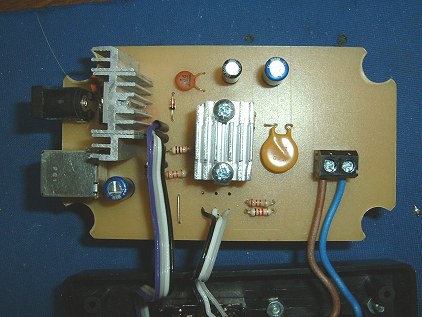
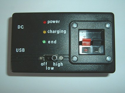
The Completed PCB & Front Panel
The HIGH setting charge curve