Part 3 ~ The Power Supply
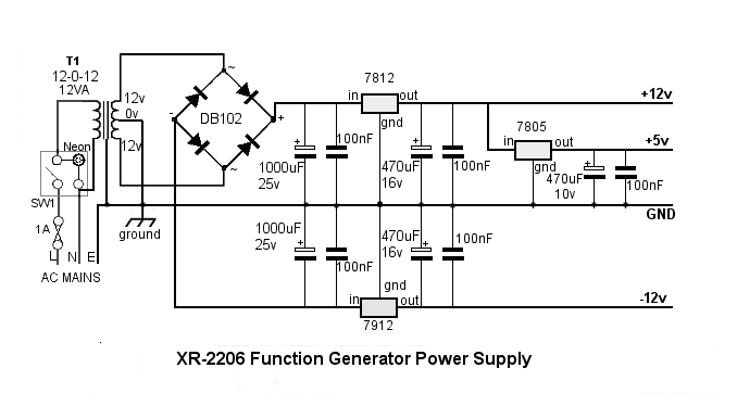
The power supply circuit is fairly conventional. It provides plus and minus 12 volts for both the XR-2206 funtion generator IC and the TL072CP OpAmp. It also provides plus 5 volts for LM239 Comparator, the 7-segment LED display and the ATmega328 display controller.
Although the XR-2206 and the TL072CP can be used with a single supply, the resulting sine and triangle waveforms would always be positive voltages with respect to zero volts. By providing a split power supply, the waveforms can be true AC waveforms with positive and negative excursions about the zero volts (ground) point.
The square wave output from the XR-2206 is always a DC voltage above 0v regardless of the power supply.
Safety Considerations
This project uses potentially lethal mains voltages. Do NOT skimp on safety arrangements such as earthing (grounding), fuses, ventilation and preventing access to live parts through ventilation slots.
Use a good quality screw-in type panel fuse and ensure that the design is such that, when removing the fuse holder, it is well clear of live internal contacts before there is sufficient clearance to be able to touch the fuse (or the holder's metal parts) with your fingers.
The mains earth (ground) lead is connected to the enclosure through one of the transformer mounting bolts. Although I used a plastic enclosure, the mains transformer mounting bolts are exposed on the underside so must be connected to mains earth.
Note that any parts of the enclosure that are attached separately (such as the front & rear panels and the top attached with self-tapping screws, for example) should have their own earth wire back to the same transformer mounting bolt. Do not rely on the self-tapping screws for earth continuity. Try to leave the incoming earth conductor longer than the live and neutral conductors so that, if the cable does get forcibly pulled, the earth will be the last conductor to break.
All exposed mains-voltage connections - to the illuminated switch, the fuseholder and the transformer - must be insulated with heat-shrink sleeving and/or access prevented with insulating covers. It should not be possible to make contact with any high voltage connections - even with the top cover removed - without a determined and conscious effort!
The mains cable entering through the rear panel must be protected from chafing with a rubber grommet and the cable must be clamped against moving inside the enclosure to prevent the connections being pulled or twisted and to prevent the grommet being pulled from its hole.
Despite what commercial products may do, do not use the printed circuit board for any mains voltage part of the circuit.
The low voltage components of the power supply are mounted on the main function generator PCB. The +12v and +5v regulators require small heatsinks. Due to lack of space, I fabricated a heatsink for the +12v regulator from a small strip of aluminium. Constructional details are shown on the next page...