Printed Circuit Board
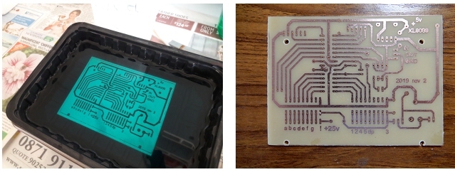
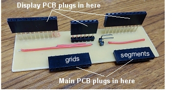 I mounted the display on its own PCB to make it easier to bring its flexible pins out to standard PCB pin headers. To avoid having too many untidy wires crossing
over between
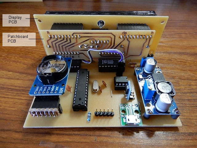
the display PCB and the main PCB, I made a "patchboard" PCB (shown left) which plugs into the display PCB and the main PCB. The patchboard allows any cross over connections to be
made on the PCB, using rigid wire links only where necessary.
I mounted the display on its own PCB to make it easier to bring its flexible pins out to standard PCB pin headers. To avoid having too many untidy wires crossing
over between
the display PCB and the main PCB, I made a "patchboard" PCB (shown left) which plugs into the display PCB and the main PCB. The patchboard allows any cross over connections to be
made on the PCB, using rigid wire links only where necessary.
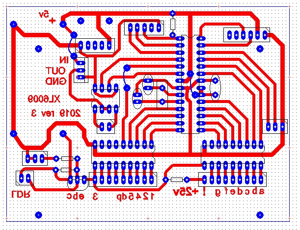
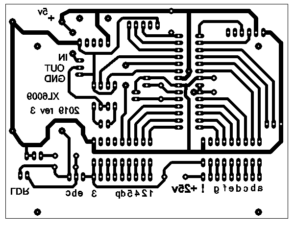
As both the display PCB and the patchboard PCB are specific to the display I used, I won't show the PCB artwork here but they
can be downloaded in PDF format here: Patchboard pdf Futaba 4-LT-46ZB3 Display PCB
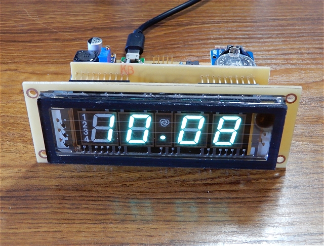
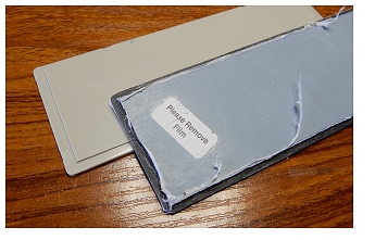 The enclosure's plastic front panel is replaced with black transparent perspex (type 923). Unfortunately, 3mm seems to be the thinnest available so I used a Dremel
router to make a copy of the original front panel.
The enclosure's plastic front panel is replaced with black transparent perspex (type 923). Unfortunately, 3mm seems to be the thinnest available so I used a Dremel
router to make a copy of the original front panel.
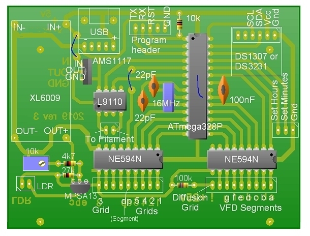
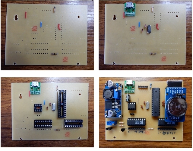
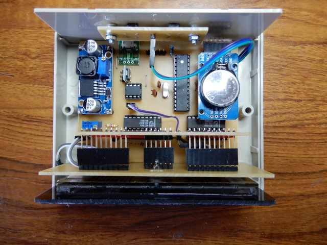
The DS3231 Clock Module is supplied with a right-angle pin header already soldered in (I do wish they wouldn't do that!) hence the odd-looking right-angle "adapter" you can see in the photo below! Unsoldering header pins from through-hole plated PCBs very often results in solder pads becoming detached so the adapter was safer. The far end of the RTC module is supported with a small plastic pillar glued to the main PCB.
One of the main PCB mounting screws is situated underneath the DC-DC boost module and is inaccessible when the module is soldered in place. I filed the mounting hole into a keyhole shape, the power module is mounted on short pillars and the PCB is slipped over the screw head.
| XL6009 DC-DC Voltage Boost Converter | eBay |
| AMS1117 5v to 3.3v DC Step Down Buck Converter | eBay, AliExpress, Bang good |
| L9110H H-Bridge 8-pin DIP | eBay, AliExpress, Hobby Components |
| NE594N VFD 18-Pin DIP Driver IC. An alternative is the UDN6118A. | eBay |
| DS1307 Clock Module. A higher precision alternative is the DS3231. | eBay |
| ATmega328P with Arduino bootloader + 2x22pF caps and 16MHz crystal | eBay, HobbyTronics |
| Vacuum Fluorescent Display | eBay |
| GL5506 Light Dependent Resistor | eBay |
| Micro USB Breakout Board | eBay |
| Hammond Enclosure 130 x 100 x 50 RM2015M | eBay, Bitsbox |
| Black tint, see through Perspex® (923), 3mm thick for front panel. | eBay |