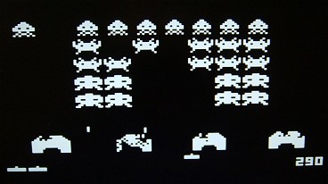
Arduino TVout
A number of commercial products based on the library have been produced, notably http://nootropic design's Hackvision and Wayne and Layne. As a bonus for the rest of us, these companies have provided Open Source "add-on" (or support) libraries of their own. All of these add to the versatility and popularity of both the TVout library and of the Arduino itself (probably!).
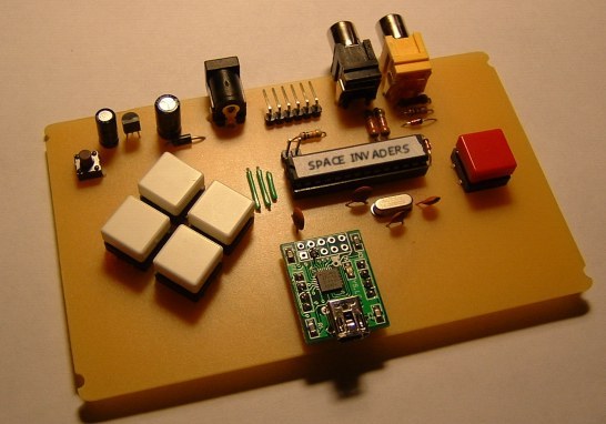
All the hardware designs based on TVout are open source and compatible with the TVout library so I decided to base a simple project on the Hackvision design. My version uses a single-sided printed circuit board because that's all I have the facilities for. As a result, it's slightly larger than the Hackvision version and doesn't have such a comprehensive set of output headers.
I've had to combine the two "paddle" headers into a single 6-way header - the intention being to wire the header to two separate 4-pin case-mounted sockets when the pcb is fitted in a case. I haven't fitted a header specifically for a Wii Nunchuk controller (as in the Hackvision design) although the two analogue pins (A4 and A5) are available on a two-pin header.
I decided at the outset to incorporate a USB-to-Serial converter breakout board to make it easy to re-program but my design still incorporates it's own 5 volt regulator instead of using the USB's 5 volt supply.
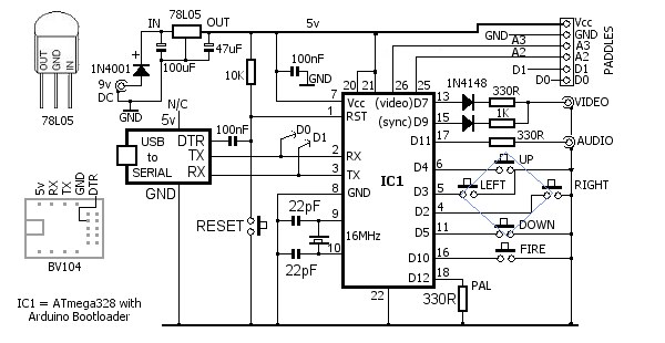
The Circuit
|
|
The nootropic design Hackvision firmware uses Arduino digitalPin 12 to determine whether the TV standard is NTSC or PAL. In the Hackvision schematic, this pin is tied directly to ground in PAL areas. The TVout library has specific software functions - begin(mode) and begin(mode, x, y) - to set NTSC or PAL, so there is some flexibility (ambiguity?) in the use of digitalPin 12. For this reason, I pulled the pin low through a 330 Ω resistor instead of tying it directly to ground. This may spare the pin from an early retirement should it accidentally be configured as an OUTPUT and pulled high with a digitalWrite.
Audio output is on digitalPin 11. As this is connected directly to the outside world, I added a 330 Ω resistor in series with the output. The solder connections inside phono plugs aren't 100% reliable (particularly in an "animated" situation such as a game console) and I feel that, without the resistor, a short circuit between the centre pin and the cable braid could send pin D11 for an early bath .
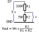 The 330 Ω resistor in series with the video output on digitalPin 7 is there to form a potential divider with a 75 Ω
resistor built into most TVs. Using "stock" value resistors, the actual voltage works out to 0.925 volts which is near enough to
the 1 volt which the TV interprets as 'white'.
The 330 Ω resistor in series with the video output on digitalPin 7 is there to form a potential divider with a 75 Ω
resistor built into most TVs. Using "stock" value resistors, the actual voltage works out to 0.925 volts which is near enough to
the 1 volt which the TV interprets as 'white'.
With a HIGH on digitalPin 9, the 1K resistor provides about 300mV from the potential divider which is accepted by the TV as the 'Black'
level. A 'low'
on this pin and on digitalPin 7 together (ie 0 volts) will then be taken by the TV as the Sync signal.
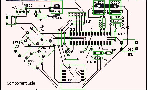
The Printed Circuit Board
I use Seno etch resist transfers to make my printed circuit boards. It's not exactly hi-tech so my board layouts tend to be simple. Although the layout of this board could have been squeezed to make the board a bit smaller, it was designed with a Maplin ABS Box in mind and I wanted an exact fit across the width so the power and phono sockets would be flush with the back edge and the USB programming socket flush with the front edge.The track-side image shown below is an exact-size scan of the actual PCB. The DC power socket and the two phono sockets need quite large holes drilling for which I don't have any Seno transfers; which explains why the layout looks a bit untidy around those areas!
 |  |