TV Sound Booster - with IR Remote Learning Function
In common with a lot of modern flat screen TVs, the sound quality on my Samsung TV is quite poor but I couldn't find a sound bar that would stand under the TV without obscuring the bottom centimetre or two of the screen and a sound base was too big.
In any event, both suffered from severe buffering; sometimes the sound would lag behind the picture and sometimes it would stop altogether in an attempt to catch up so I decided to build a simple sound "booster" or "enhancer" of my own.
I tested a few Bluetooth power amplifier modules but nearly all of them insisted on making a verbal announcement whenever they re-connected with the TV. As the connection was broken every time the TV was switched to standby, it was clear that it would very soon become an annoyance. Also, none of the modules I tested had provision to adjust the volume.
So I tested the TV's optical output option using a simple,inexpensive Optical (TOSLINK) to RCA converter. I wanted to be able to adjust the volume using the existing TV Infra Red remote but, as both the optical and the Bluetooth outputs from the TV are at a fixed volume, a pre-amplifier with some sort of IR "learning" capability was required. The ability to adjust the treble, bass and balance would be an advantage - even if these were just used during the setup procedure.
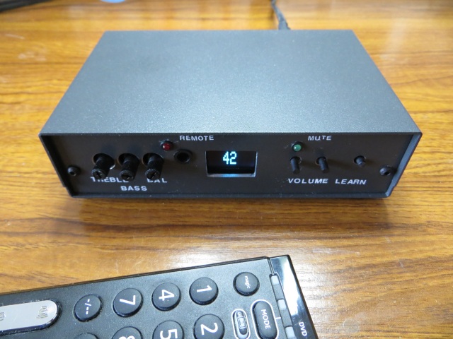
I wanted a smallish unit that would sit under the TV (on top of the DVR) and considered that 8 to 10 watts per channel would be sufficient - especially if it was used "in tandem" with the existing TV sound. After some research and experimentation on breadboards, the following circuit evolved:
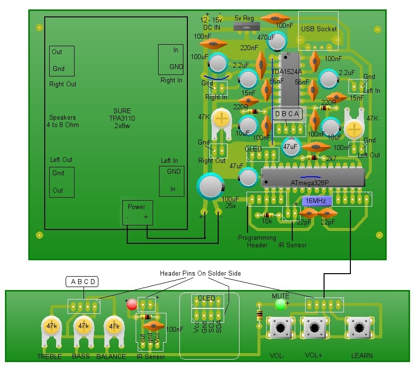
The Circuit
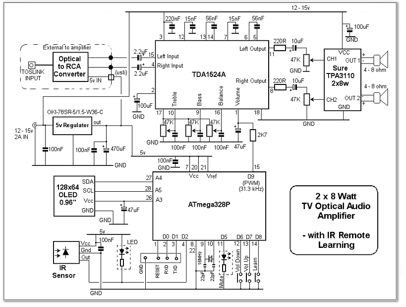
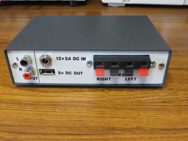
Optical audio from the TV is converted to a standard RCA Line In signal using the extenal Optical to RCA converter - widely available on Amazon and eBay for around 5 UK pounds. I decided to keep the converter external to the amplifier and provide a 5v DC output from the amplifier to power the converter.
TDA1524A
The TDA1524A stereo preamplifier IC is ideal for this application: Volume, Treble, Bass and Balance are all adjustable using a 0 - 5v DC voltage instead of messing around with dual-gang stereo potentiometers. As I anticipated that the tone and balance controls would be used infrequently, I used simple preset potentiometers with thumb adjusters on the front panel for these functions - wired exactly as shown in the datasheet.
ATmega328P
The 0 - 5 volts for the volume control is, instead, derived from a PWM output from theATmega328P. As the default PWM frequency is around 490Hz, even with some filtering, it would be difficult to remove this from the audio signal so the Arduino Sketch sets the PWM frequency on pin 15 (Output D9) to 31.3kHz - well outside the audible range so simple filtering can be used with a 2k7 resistor and 47uF capacitor. The resulting 0 to 5v signal is applied to the TDA1524A's Volume control pin: pin 1.
 Volume can be adjusted by pressing two tactile switches connected to ATmega328P inputs D6 and D7. Pressing them ramps up or down the PWM signal on D9.
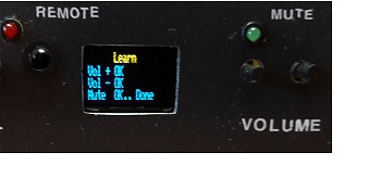
A third tactile switch (connected to D8), puts the Arduino Sketch into "Learning Mode" in which an IR sensor (connected to D2) captures signals from
the TV's remote control, saves them in EEPROM, and uses them as Volume UP, Volume DOWN and MUTE when the sketch switches
back to normal running mode. The ATmega328P only has to be taught once as the codes are stored in non-volatile memory and the codes can simply be
over-written if you want to use different buttons on the remote at a later date.
Volume can be adjusted by pressing two tactile switches connected to ATmega328P inputs D6 and D7. Pressing them ramps up or down the PWM signal on D9.
A third tactile switch (connected to D8), puts the Arduino Sketch into "Learning Mode" in which an IR sensor (connected to D2) captures signals from
the TV's remote control, saves them in EEPROM, and uses them as Volume UP, Volume DOWN and MUTE when the sketch switches
back to normal running mode. The ATmega328P only has to be taught once as the codes are stored in non-volatile memory and the codes can simply be
over-written if you want to use different buttons on the remote at a later date.
During the learning process, a 0.96" OLED I2C display connected to ATmega328P pins A4 and A5, prompts the user which button on the remote the Sketch is waiting for the code for. Additionally, it lights up for 1.5 seconds to show the volume setting whenever the volume is adjusted and when the sound is un-muted. The 5v Vcc supply to the OLED is provided by ATmega328P output A3 (configured as a digital output). This allows the display to be switched off when it's not actually required in order to save a small amount of power and to avoid distraction when watching the TV.
During initial testing on a breadboard, the OLED caused some interference on the audio when it was powered on. Although this was another reason to power the OLED down when it wasn't required, there is actually no sign of interference with the project properly built with decent earthing on a PCB.
TPA3110
I used a Sure TPA3110 2x8W module for the power amplifier as it is widely available from many sources and I wasn't looking for a huge output. As I found it was possible for the output from the TDA1524A to easily overload the power amp's inputs, I used a couple of 47k preset potentiomenters to limit the signal level. They also act as a course balance adjustment.I used a small "buck" regulator for the 5v DC supply to the ATmega328P, the OLED display (through an ATmega328P output) and the IR Sensor. Unlike a standard 7805 regulator, the OKI-78SR-5 wastes virtually no power and runs cold. A USB A socket is fitted on the PCB to provide a 5v supply to the external Optical-to-RCA Converter. The TDA1524A pre-amp and the TPA3110 Power amp are connected directly to the 12 - 15 volt DC supply.
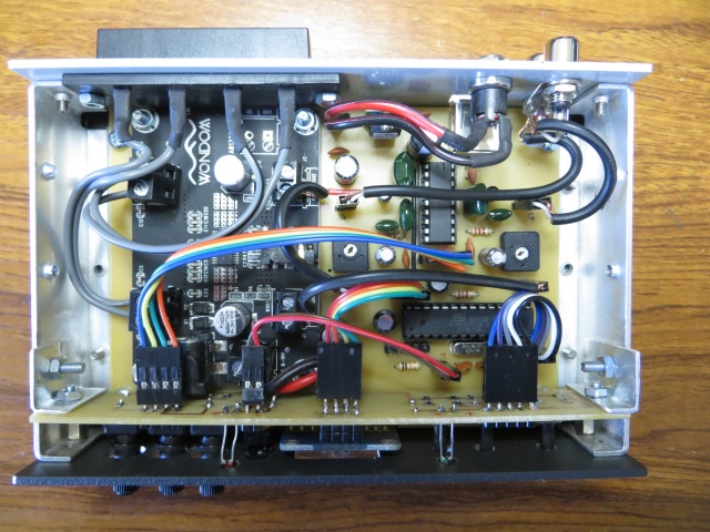
The Printed Circuit Board
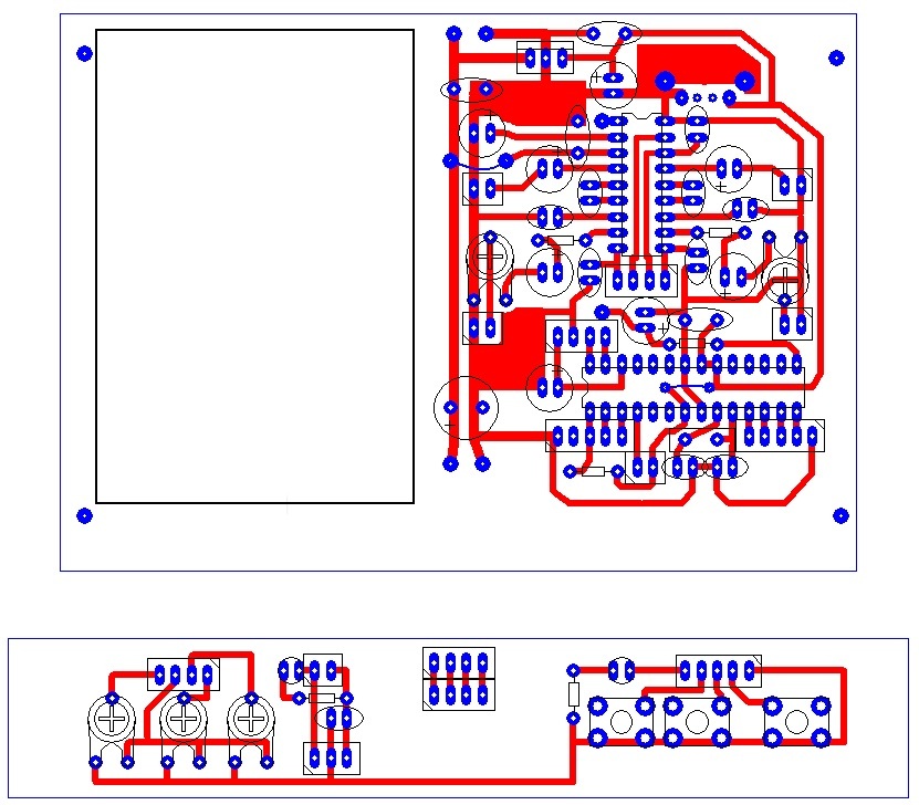
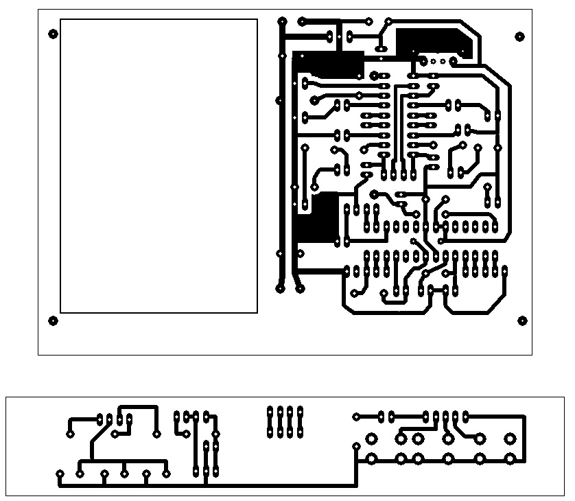
Download artwork for PCB Wizard Download artwork in PDF format
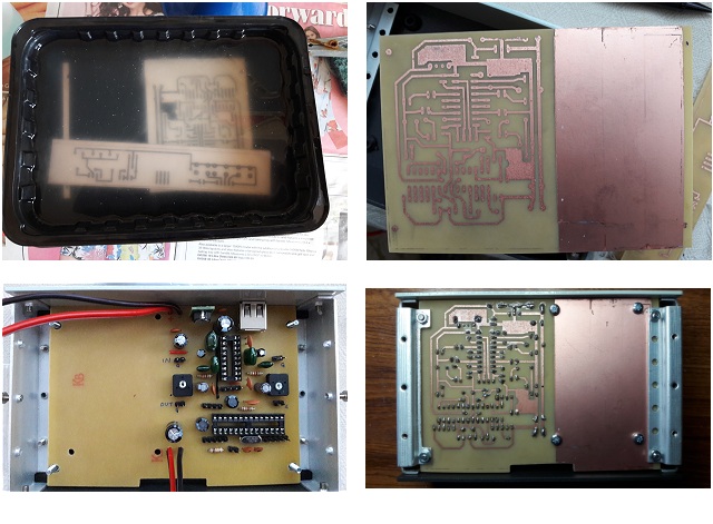
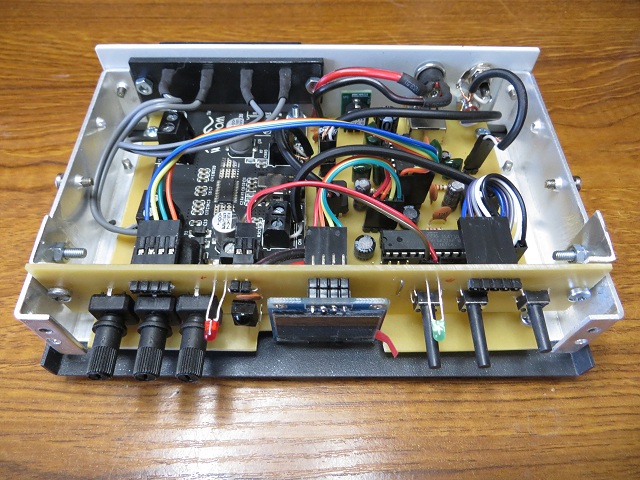
Construction
Required Additional Arduino Libraries
Adafruit_GFX.hAdafruit_SSD1306.h
IR Remote Library
Arduino Sketch
#include <IRremote.h>
#include <EEPROM.h>
#include <Adafruit_GFX.h>
#include <Adafruit_SSD1306.h>    // Adafruit 0.96" OLED Library

#define oledAddress 0x3c        // Banggood oleds I2C address differs from Adafruit oleds.

int SDIO = A4;                  // I2C bus for OLED Display.
int SCLK = A5;

Adafruit_SSD1306 oled(12);       // Initialise Adafruit library

int oledVcc = A3;                // 5v supply for OLED


int RECV_PIN = 2;                // Infra Red input to ATmega328

IRrecv irrecv(RECV_PIN);         // Initialise IR library

decode_results results;

long RemoteVolUp;                // My remote's code = 0xe0e0e01f;
long RemoteVolDown;              // = 0xe0e0d02f;
long RemoteMute;                 // = 0xe0e0f00f;

long lastCode = 0;
unsigned long timer = 0;
unsigned long timerLed = 0;

unsigned long volumeTimer = 0;

bool muteLedOn = true;
bool volumeTimerOn = false;


int PWM = 9;                   // Frequency increased to 31372.55 Hz in setup.

int learn = 8;

int VolUp = 7;                 // Volume Up button.
int VolDown = 6;               // Volume down button

int mutedLed = 5;              // Flash LED when sound is muted


int Volume = 255;
int volumeOffset = 40;         // 0 to 39 is virtually silent so make range 40 - 100.
bool isMuted = false;

void setup (void) {
TCCR1B = (TCCR1B & 0b11111000) | 0x01;     // Set PWM frequency on pins 9 & 10 to 31372.55 Hz

  Serial.begin(9600);

 pinMode(oledVcc, OUTPUT);                 // 5V supply to OLED display
 pinMode(mutedLed, OUTPUT);                // Flash an LED while FM62429 volume is muted.

 pinMode(VolDown, INPUT_PULLUP);           // Push buttons for Volume Up, Volume Down and
 pinMode(VolUp, INPUT_PULLUP);
 pinMode(learn, INPUT_PULLUP);             // Learn remote codes.

 irrecv.enableIRIn();                      // Start the receiver

 RemoteVolUp = EEPROMReadlong(1);          // Read remote codes that have previously
 RemoteVolDown = EEPROMReadlong(5);        // been saved in EEPROM. Each code is
 RemoteMute = EEPROMReadlong(9);           // 4 bytes in length.

 if (EEPROM.read(0) <= 255) {              // Read last volume setting from EEPROM.
  Volume = EEPROM.read(0);
 }
 analogWrite(PWM, Volume);                        // Set  volume .
}

void startOled() {                                 // OLED causes some interference to
  digitalWrite(oledVcc, HIGH);                     // the audio so it is only powered
  oled.begin(SSD1306_SWITCHCAPVCC, oledAddress);   // up and initialised when required.
  delay(50);
  oled.clearDisplay();
  oled.setTextColor(WHITE);
}

void learnRemote() {                               // Routine to receive remote codes for
  startOled();                                     // Volume Up, Volume Down & Mute and
  oled.setTextSize(1);                             // save them in EEPROM.
  oled.setCursor(40,0);
  oled.print("Learn");
  oled.setCursor(5,8);
  oled.print("Vol + ");
  oled.display();
  results.value = 0;
  while (results.value == 0) {
    if (irrecv.decode(&results)) {
    //Serial.println(results.value, HEX);
    irrecv.resume(); // Receive the next value
    delay(100);
    }
  }
  RemoteVolUp = results.value;
  oled.print("OK");
  oled.setCursor(5, 16);
  oled.print("Vol - ");
  oled.display();
  results.value = 0;
  while ((results.value == 0) || (results.value == RemoteVolUp)) {
    if (irrecv.decode(&results)) {
    // Serial.println(results.value, HEX);
      irrecv.resume(); // Receive the next value
      delay(100);
    }
  }
  RemoteVolDown = results.value;
  oled.print("OK");
  oled.setCursor(5, 24);
  oled.print("Mute ");
  oled.display();
  results.value = 0;
  while ((results.value == 0) || (results.value == RemoteVolDown)) {
    if (irrecv.decode(&results)) {
      //Serial.println(results.value, HEX);
      irrecv.resume(); // Receive the next value
      delay(100);
    }
  }
  RemoteMute = results.value;
  oled.print(" OK.. ");
  oled.print("Done ");
  oled.display();

  if (EEPROMReadlong(1) != RemoteVolUp) EEPROMWritelong(1, RemoteVolUp);
  if (EEPROMReadlong(5) != RemoteVolDown) EEPROMWritelong(5, RemoteVolDown);
  if (EEPROMReadlong(9) != RemoteMute) EEPROMWritelong(9, RemoteMute);
  delay(3000);
  digitalWrite(oledVcc, LOW);
  lastCode = RemoteMute;
  isMuted = false;
  analogWrite(PWM, Volume);
}


void loop (void) {

  if (digitalRead(learn) == LOW) {
    while (digitalRead(learn) == LOW);
    learnRemote();
    delay(100);
  }

  results.value = 0;

  if (irrecv.decode(&results)) {
    Serial.println(results.value, HEX);
    irrecv.resume(); // Receive the next value
    delay(80);
  }

 if ((digitalRead(VolUp) == LOW) || (results.value == RemoteVolUp)) {
  if (Volume < 255) {
    Volume++;
    analogWrite(PWM, Volume);
    isMuted = false;
    lastCode = results.value;
  }
  showVolume();
  if (digitalRead(VolUp) == LOW) delay(100);
 }

 if ((digitalRead(VolDown) == LOW) || (results.value == RemoteVolDown)) {
  if (Volume > volumeOffset) {
    Volume--;
    analogWrite(PWM, Volume);
    isMuted = false;
    lastCode = results.value;
  }
  showVolume();
  if (digitalRead(VolDown) == LOW) delay(100);
 }

 if ((results.value == RemoteMute) && (lastCode != RemoteMute)){
     timer = millis();
     if (!isMuted) {                                      // The same IR code is used to mute and
      analogWrite(PWM, 0);
                                                          // unmute. Remote may send the code
      isMuted = true;                                     // more than once for one button-
      timerLed = millis();                                // press so ignore 2nd and subsequent
     } else {                                             // codes.  Start a timer so that the
      analogWrite(PWM, Volume);                           // 'ignore' flag can be reset one
      showVolume();                                       // second after no more 'mute' codes
      isMuted = false;                                    // are received.
     }                                                    // Next time the code is received must
     lastCode = results.value;                            // mean 'toggle' the mute setting.
  }

  if (millis() - timer > 1000) {                          // Reset the 'ignore mute code' flag.
   lastCode = 0;
  }

  if (millis() - timerLed > 250) {                          // Set up flashing output for
    muteLedOn = !muteLedOn;                                 // 'muted' LED
    timerLed = millis();
  }

  digitalWrite(mutedLed, (muteLedOn && isMuted));            // Flash 'muted' LED if muted.

  if ((millis() - volumeTimer > 1500) && volumeTimerOn) {    // Turn off OLED display after
    volumeTimerOn = false;                                   // 1.5 seconds and write new
    digitalWrite(oledVcc, LOW);                              // volume setting to EEPROM.
    if (EEPROM.read(0) != Volume) {
       EEPROM.write(0, Volume);
    }
  }

}

void showVolume() {
  if (!volumeTimerOn) {                                     // If OLED is not already powered,
    startOled();                                            // power it up.
    oled.setTextSize(3);
  }
  oled.clearDisplay();
  oled.setCursor(40,8);
  oled.print(map(Volume, volumeOffset, 255, 0, 100));       // 40 to 255 for Pre-amp IC = 0 to 100 for display
  oled.display();

  volumeTimerOn = true;                                     // Flag that the display timer is running
  volumeTimer = millis();                                   // Start the display timer.
}


void EEPROMWritelong(int address, long value) {
    //Decomposition from a long to 4 bytes by using bitshift.
      //One = Most significant -> Four = Least significant byte
      byte four = (value & 0xFF);
      byte three = ((value >> 8) & 0xFF);
      byte two = ((value >> 16) & 0xFF);
      byte one = ((value >> 24) & 0xFF);

      //Write the 4 bytes into the eeprom memory.
      EEPROM.write(address, four);
      EEPROM.write(address + 1, three);
      EEPROM.write(address + 2, two);
      EEPROM.write(address + 3, one);
}

long EEPROMReadlong(long address)  {
      //Read the 4 bytes from the eeprom memory.
      long four = EEPROM.read(address);
      long three = EEPROM.read(address + 1);
      long two = EEPROM.read(address + 2);
      long one = EEPROM.read(address + 3);

      //Return the recomposed long by using bitshift.
      return ((four << 0) & 0xFF) + ((three << 8) & 0xFFFF) + ((two << 16) & 0xFFFFFF) + ((one << 24) & 0xFFFFFFFF);
}