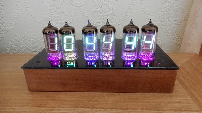
IV-12 (ИB-12) Vacuum Fluorescent Display Clock
Although the VFD Clock using a multi-digit VFD display is a good place to start, designs using a separate VFD tube for each digit can be very attractive. Unfortunately, all the commercially available kits tend to be expensive. Somewhere around 140UKP is typical.Building one from scratch has to be less expensive. It obviously depends on what parts you already have in your "spares box" but six vintage Russian IV-12 (ИB-12) tubes are available on eBay (from Russia) for around 10UKP and other specialized parts are availabke for a few UK pounds each. I built the whole project for around 25UKP - including some "development parts" that I didn't use in the final design.
There are two main display contenders for a vacuum fluorescent display clock with separate digits: The IV-11 and the IV-12. The IV-11 has a decimal point in addition to the 7 segments and would seem better suited than the IV-12 which does not have a decimal point. However, the IV-11 has 11 flying leads while the IV-12 has more traditional valve (vacuum tube) pins at its base.
When you consider both types have been out of production for decades and we're reliant on "new from old stock", mainly from Russia where they were manufactured, the IV-12 is the better option as it will be much easier to replace a tube should it become necessary.
They are available from a few suppliers on eBay and I will provide a few links at the end of this article. One piece of advice: Try to find a supplier that advertises the tubes as a matched set. I failed to do that and there is a noticeable difference in brightness, especially if they're run with a lower filament and/or grid voltage: It's a good idea to run them a little below their maximum voltage ratings, especially during development.
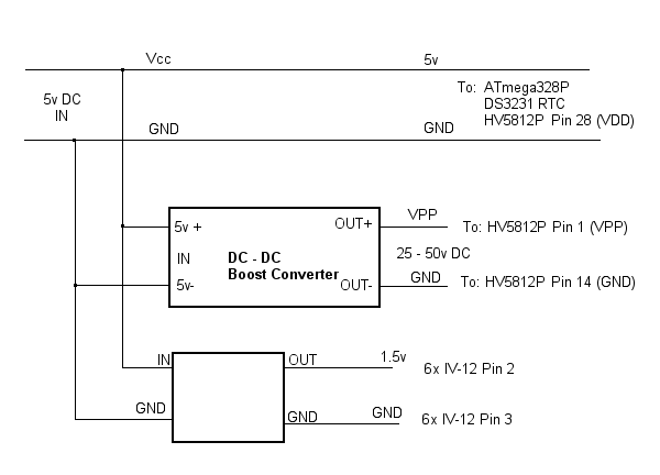
The project uses two DC to DC converters: A 5 volt to 50 volt boost converter for the IV-12 tubes' grids and anodes and a 5 volt to 1.5 volt buck converter for the tubes' filaments.
Note that, as the IV-12 tubes are not breadboard-friendly, I had to use the printed circuit board for some of the design's development. Although the schematic and the PCB artwork shown here are correct (as far as I'm aware), some of the photographs taken during construction do not necessarily correspond with the PCB artwork. Also, the footprint of your two DC to DC converters, in particular, may differ from mine so don't copy the PCB artwork verbatim without first checking that your components will fit!
The Main Circuit
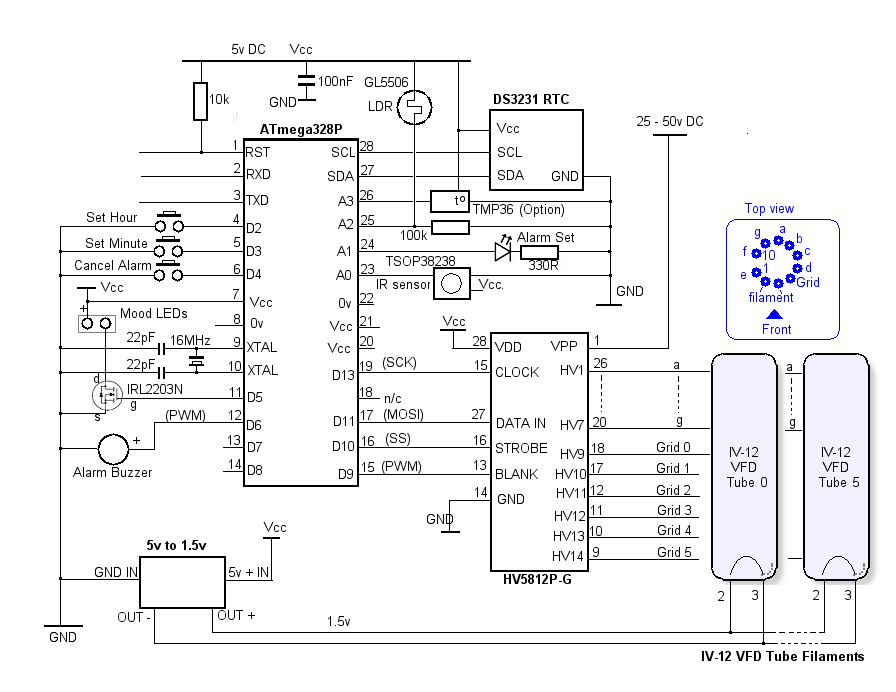
The six IV-12 tubes are driven in a multiplexed fashion using the HV5812P-G, which is basically a 20-bit shift register with logic-level inputs and high voltage parallel outputs. Only 13 of the outputs are used - 7 for the tubes' 7-segment anodes (the corresponding segment of all six tubes being connected in parallel) and 6 for each individual tube's grid. The HV5812P-G is a 28-pin 0.6" wide PDIP package which makes it ideal for a simple single-sided home-manufactured PCB.
The process to display digits on the IV-12 tubes is as follows:
- All outputs from the HV5812P-G are first turned off by taking the BLANK input (pin 13) HIGH.
- The HV5812P-G's shift register is then enabled by taking its STROBE pin LOW.
- Data representing the tubes' grids is first clocked into the HV5812P-G. Although 8 bits are clocked in, only the first 6 bits are used and only one of those will be a '1' - representing the tube we are currently updating.
- Data representing the 7 segments of that tube's numerical digit is then clocked in. Again, 8 bits are clocked in, the Most Significant Bit is always zero.
- The remaining 4 bits which make up the HV5812P-G's full 20-bits are ignored. The HV5812P-G doesn't seem to care that the extra bits haven't been clocked in.
- Once all the data has been clocked into the shift register, it is copied to the HV5812P-G's output latch by taking the STROBE pin HIGH.
- Finally, the contents of the output latch are transferred to the actual high voltage output pins by taking the BLANK pin LOW.
The 7-segment data will appear on pins HV1 - HV7 and one pin from HV9 to HV14 will be high depending on which tube's grid is to be activated.
- The process is repeated, shifting the '1' bit representing the grid to the left by one bit each time untill all six tubes have been updated.
The segment and grid data for the HV5812P-G is controlled using an ATmega328P; the HV5812P-G CLOCK, DATA IN and STROBE inputs are fully compatible with the ATmega328P's hardware SPI pins which makes transferring the data really simple.
The brightness of the IV-12 tubes can be controlled by applying a PWM signal to the HV5812P-G BLANK input.
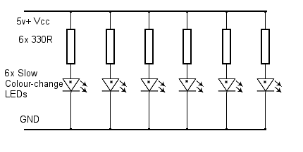
The colour-changing "mood LEDs" (shown in the circuit below) are simply six slow-colour-changing LEDs. Unfortunately, due to their nature, it's not possible to control their brightness using PWM, however off and on times for the mood LEDs can be set in software using the IR remote.
The IV-12 Filament Supply
The IV-12 tubes require a 1.5v filament supply. Initially, I tried the tubes with the filaments wired in series. This allowed for a more-easily-obtainable 5v to 9v DC to DC boost converter ( 6x 1.5v = 9v). However, the display didn't look good at all. Presumably, variations in the tubes' resistance was affecting the exact voltage across each filament.This is the first major difference you may spot between images of the PCB artwork and actual photos of the PCB as I had to cut tracks and modify the PCB to wire the filaments in parallel at 1.5 volts instead. The schematic shows the final, working circuit and, hopefully, the PCB artwork shown here should match.
Soldering in the "bases" for the IV-12s was such a fiddly and tedious job that I didn't have the heart to etch a new PCB and start again from scratch!
Wired in parallel, the filaments take a total of about 500mA. According to the datasheet, the filament current is 100mA ± 10mA so, in the worst case, that could rise to about 660mA at 1.5 volts.
The ATmega328P
The rest of the circuit around the ATmega328P is standard stuff. The Real Time Clock uses an I2C module connected to the SCL and SDA pins.The signal from a TSOP38238 Infra Red 38kHz receiver is connected to ATmega328P A0 pin (configured as a digital input). All of the clock's functions can be controlled using a cheap IR remote but the ability to set the clock time and cancel the alarm using push buttons is also available in case the IR remote isn't to hand.
I also included a simple analogue temperature sensor, connected to analogue input A3. As the IV-12 tube has no decimal point, the temperature is shown to the nearest 1 degree. The accuracy of the TMP36 temperaure sensore is only around ±2 degrees anyway. I included it because most of the expensive clocks have it so I thought mine should too! I use it to measure the internal temperaure of the clock's enclosure.
A light dependent resistor is connected to analogue input A2 to measure ambient light. In conjunction with the PWM output at D9 it is used to control the Blanking input on the HV5812P-G VFD driver in order to dim the display as ambient light decreases.
ATmega328P output D6 is used as an output to drive a simple low current PC buzzer to act as an alarm. It's a PWM output so either self-oscillating or simple DC speakers should be suitable. The alarm is set and reset using either the push button connected to ATmega328P input D4 or by using the IR remote. An LED connected to A1 (configured as a digital output) indicates when the alarm is set.
ATmega328P output D5 controls the gate of an IRL2203N N-Channel MOSFET. It simply switches 5 volts to a 2-pin socket for connecting a string of LEDs for "mood lighting." I just used six slow colour-changing LEDs which poke up through a hole between each IV-12's pins. The IRL2203N is more than enough for this job but I included it in case I wanted a more sophisticated (higher current) mood lighting system with its own processor at a later date. As mentiond above, it's not possible to control the brightness of the colour-chaning LEDs using simple PWM but on and off times can be set to enable them to be turned off automatically at night.
There are two spare IO pins on the ATmega328P (D7 and D8) which could be used for green LEDs to act as separators between hours, minutes and seconds but I didn't include this.
IV-12 (ИB-12) Datasheet (in Russian)
The Power Supply
IV-12 Basic data
================

Voltage filament, V ..................................... 1.5 ± 0.15
Heating current, mA ..................................... 100 ± 10
Anode segment current, mA ...................... ........ 3.5 ± 1.5
Grid Voltage, V ......................................... 25
Grid current, mA ........................................ 12 ± 5

Grid voltage pulsed, V .................................. 50

Minimum operating time, h ............................... 10,000


Maximum allowable electrical conditions
=======================================

Voltage filament, V ..................................... 1.25 - 1.65

Static mode
-----------

The highest voltage of the anodes-segments, V ........... 30
Maximum current of one anode segment, mA ................ 0.9
The maximum grid current, mA ............................ 20

Pulse mode
----------

The highest voltage of the anodes-segments, V ........... 70
The greatest voltage of a grid.. ........................ 70
The 5v to 1.5v DC to DC buck converter is shown on the main schematic but it's also shown below for completeness. Note that, according to the Russian datasheet for the IV-12 display, a conductive coating inside the tube acts as an electrostatic shield and is connected to filament pin 3. The tube segments seem to display more uniformly if this pin is connected to Ground. The datasheet for the IV-12 says the filament current is 100mA ±10mA at 1.5v so a DC to DC converter rated at 1A minimum should be used.
There are several ways to derive 1.5 volts from the main 5 volt supply. Initially I tried what's described on eBay as a "Mini-360 MP2307 DC-DC Step Down Buck Module Converter." Unfortunately its tiny pre-set potentiometer made voltage adjustment at 1.5 volts much too sensitive so I advise that you avoid those. Eventually, I used a buck converter with pre-set voltages available by bridging a selection of solder pads.
The 5v to 50v Boost converter should be capable of at least 50 volts. The more common modules only output up to 26 or 30 volts so you may need to shop around. In practice, I didn't find much difference in the display brightness when I increased the voltage above about 40 volts so there didn't seem much point in driving the converter to its limit.
The entire project, complete with mood LEDs, takes about 350mA at 5 volts.
The Mood LEDs