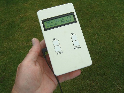
Walk-Pal FM Tuner, Altimeter, Barometer, Compass
During the development of the Picaxe Weather Station I'd aquired a couple of sensor breakout boards that, ultimately, I didn't use. I devised this little project basically to make use of these spare parts that would otherwise be lying around unused.
In addition, I'd recently bought the an Si4703 FM Tuner Breakout Board.
HMC6352 Compass Module
The compass module is the HMC6352 available from Sparkfun Electronics .This module does not have any tilt compensation but I would have found it difficult to justify the cost of a tilt compensated version - the HMC6343 - for what is, after all, just a "novelty" project.
BMP085 Barometric Pressure &Temperature Sensor
There are a couple of variations of breakout boards available for the BMP085. The version from Sparkfun needs a 3.3 volt supply. The version from Adafruit has an on-board 3 volt regulator so it "5 volt ready".The version I had as a spare was the Adafruit 5 volt version but, as this project requires a 3.3 volt regulator anyway (for the FM tuner), the Sparkfun version would be equally suitable (with suitable modifications to the PCB layout).
The Si4702 FM Radio Tuner
At the heart of the tuner breakout board is, of course, the Si 4702/03 FM Radio Tuner IC from Silicon Labs.
The Ciruit
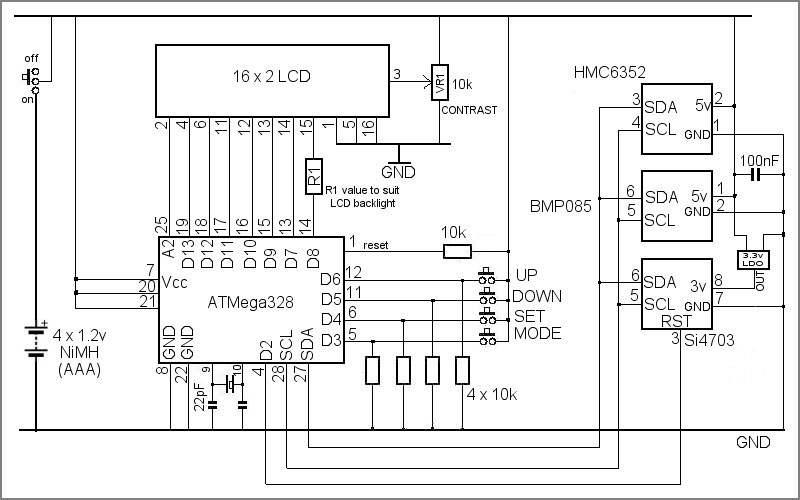
As space is limited in the case I had available, there wasn't room for an LCD piggy-backed serial driver so I opted to use a parallel interface 16 x 2 display from Oomlaut.
Some LCDs have timing "issues" with Arduino Sketches so I decided to power the LCD from an Arduino output pin. By this means, the ATMeag328 is fully up and running (including the initialization of the I2C interface) before the LCD is powered on. As all the Digital pins were already in use, I used Analoge pin A2 as a digital output pin.
I used Digital output D8 in order to turn the LCD backlight on and off.
D7 and D9 to D13 perform the usual LCD parallel interface functions. Note that these pin assignments are different from the Arduino LCD "Hello World" example. I swapped the pins around to simplify the PCB layout.
D6, D5, D4 and D3 are configured as inputs for the buttons: UP, DOWN, SET and MODE.
The actions of the buttons are determined purely in software. I have them as follows:
- UP: Steps up the pre-set radio channels OR Scans up the FM radio frequencies (depends on the MODE setting) unless SET function is active.
- DOWN: Steps down the pre-set radio channels OR Scans down the FM radio frequencies (depends on the MODE setting) unless SET function is active.
- SET: Cycles through Volume, Set Sea Level Pressure, Set Backlight Timer, Normal Operation. UP and DOWN buttons change values.
- MODE: Toggle between Pre-set Radio stations and Scan mode.
The current MODE is written to non-volatile EEPROM along with the current pre-set channel and the currently-selected scan frequency. These values are recalled when the power is next turned on. The volume setting and backlight timer are similarly saved and recovered.
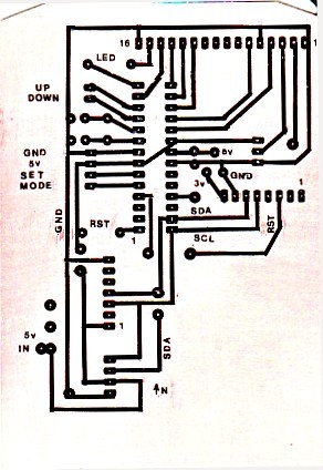 |
The PCB layout is shown on the left and, below, the actual PCB during soldering operations. The left image shows 5 wire links. The
top link is shown as R1 on the circuit diagram and controls the LCD backlight current (and brightness). The LCD I used specified a
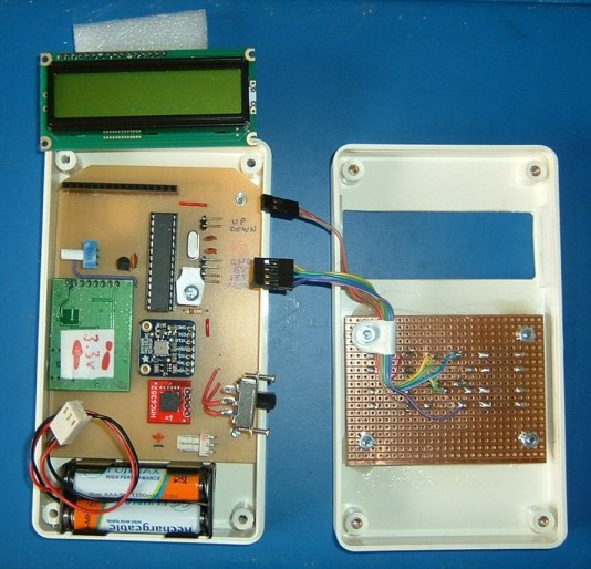
direct link to 5 volts. The single resistor shown on the PCB pulls the ATMega328's RESET pin to 5 volts. The hole just above the resistor is for a stand-off pillar to support the LCD and can be seen in the bottom photo. The image below, right, shows all the on-board components - except the three breakout boards - soldered in place. Note that I had to pack up the 16-pin LCD header socket with a strip of plain perf-board (or Veroboard with the copper removed). This was necessary to bring the front of the LCD flush with the front of the case. This meant using a stackable 16-pin header to ensure the pins were long enough to reach through the PCB. The right-angle headers to the right of the 16MHz crsytal are for connection to the four front-panel-mounted tactile switches and +5v and Ground. The connector bottom right is for the battery plug. | 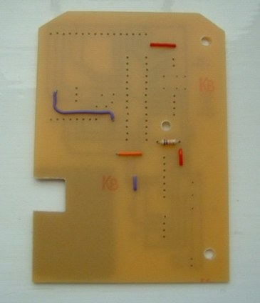 | 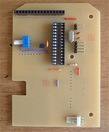 |
Downloads
Arduino Sketch & Circuit Wizard PCB Layout