Arduino - Brake Lights Tester
We're advised to check our vehicle's lights and tyre pressures regularly. Although the tyre pressures and most lights are easy enough to check, when we're on our own the brake lights are a bit trickier.
I wanted a device that doesn't need wiring into the car's electrical system. Something as quick and easy to use as the little 'pencil' type of tyre pressure gauge is what I had in mind.
One device I've seen on the US market consists of a telescopic tube which wedges between the brake pedal and the steering column to hold the pedal down while you walk round the car.
Our tester is a bit more sophisticated than that (of course!).
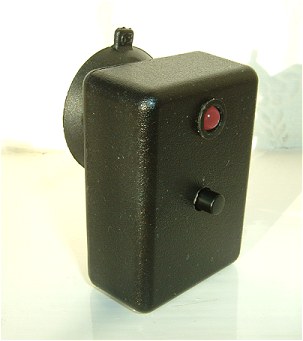
It's a small box, about the size of a matchbox, that can be kept in the boot or the glovebox (together with the tyre pressure gauge) and it makes testing the brake lights a 30-second job as simple as checking the other lights and simpler than checking the tyre pressures.
How to Use the Tester
- Switch all the tail lights off if they're in the same tail light clusters as the brake lights.
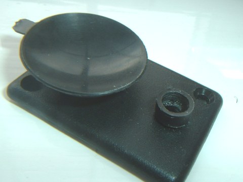
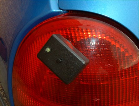
- Stick the tester to the brake light lens using the built-in suction cup.
- Press and release the TEST button.
- While the red LED is flashing move away from the tester.
- When the red LED goes steady (after about 3 seconds) the tester will measure the ambient light and will start 'looking' for the brake light to come on.
- While the red LED is steady, press the brake pedal (the ignition will probably need to be on).
- Check the LED on the tester. A green LED means the brake light came on.
- Test the other brake light(s) in the same way.
Caution!
The tester works by measuring the difference in light level between the ambient light and the additional light from the brake light. It will work better in shaded conditions with its light sensor as close to the actual brake light bulb, within the cluster, as possible. Be careful not to let the ambient light increase once the red LED has stopped flashing or it may be mistaken for the brake light coming on. The three seconds of flashing red LED is to give you time to ensure you're not shielding the tester from ambient light when it takes the ambient measurement.
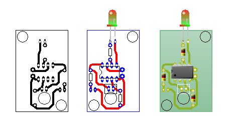
The Circuit
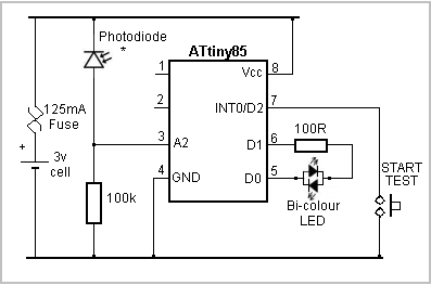
The tester is built around an ATtiny85 microcontroller which is programmed through the Arduino Editor.
Analogue pin A2 monitors the voltage at the junction of the photodiode and the 100k resistor. 100k seems the best value to give sufficient current through the photodiode/resistor while providing the largest volt drop at pin A2.
The program (sketch) puts the ATtiny85 into full Power_Down mode after 30 seconds and the only way to wake it is through a 'falling edge' interrupt on pin INT0/D2 through the START TEST button to ground. The button doesn't need a pullup resistor because the software enables the ATtiny85's internal pullup resistor.
In Power_Down, the circuit uses about 2uA (less if the photodiode is kept in the dark) so I didn't bother including an on/off switch.
As with all portable projects in which size is a consideration, the choice of battery causes the most trouble. The circuit will easily run on two 1.5v LR44 button cells in series but I wasn't able to find a suitable holder. I decided to use a 110mAh lithium-polymer battery which I had spare - hence the inclusion of the 125mA resettable fuse. A CR2032 cell would also be suitable, probably with a slightly larger enclosure to accomodate the CR2032's holder.
The value of the LED series resistor is a bit of a compromise between keeping current consumption low and having the LED bright enough to see reasonably easily. You may want to experiment with the value to suit your own requirements.
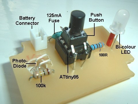
Components
- IC: ATtiny85
- Photodiode: TEPT5700
- Bi-colour LED. 5mm.
- Battery Connector: JST PH 2mm (or to suit alternative battery)
- 6mm tactile push button and cap.
- 100R resistor, 100k resistor.
- 125mA resettable fuse (optional).
- Suction Cup: Aquarium supplier.
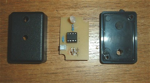
- Enclosure: Hammond Miniature General Purpose ABS Box 1551 Series Black 50x35x17mm (Maplin Code: N78BQ).
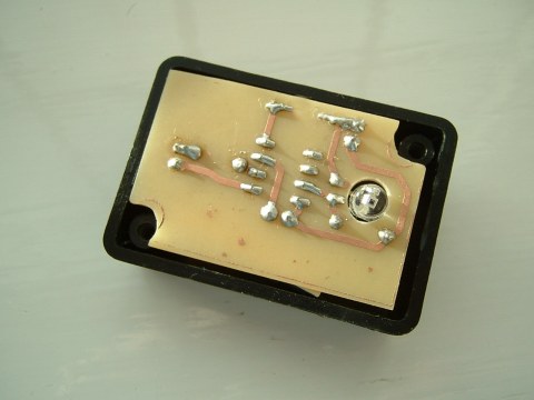
Construction
The photos below show the construction. Most is fairly self-explanatory. The 6mm tactile button is attached to the top of the ATtiny85 with a small square of double-sided sticky tape. Once the PCB is fitted in the enclosure, the switch can't move anyway.