AD9833 Waveform Generator
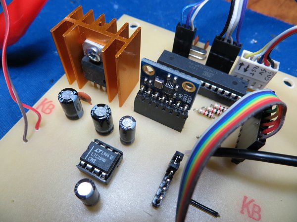
The Circuit

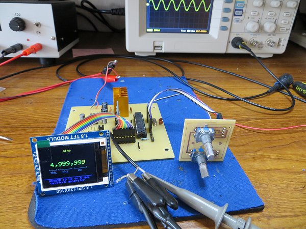
This circuit is very similar to the one I used in my AD9850 Waveform Generator. I built it to try out the AD9833 module for comparison. The main difference between the two circuits is that the AD9833 module shares the ATmega328 hardware SPI bus with the 1.8" TFT display.
The TFT Display
Sharing the hardware SPI bus caused some software problems which needed to be resolved. Initially, I couldn't get the Adafruit ST7735 display library to share the SPI bus so I switched to a slightly different TFT display module from BangGood which uses a version of the Adafruit library that has been modified by QDTech for their own display hardware and which uses the Samsung S6D02A1 controller.However, it seems "pot luck" as to whether you get a display with an ST7735 controller (which works with the standard Adafruit_ST7735 library) or a display with the Samsung controller (which needs the Adafruit_QDTech library). There doesn't seem to be any simple way to tell the displays apart except to try each library and see which works. Having resolved the software issue that was preventing the ST7735 from working initially, I've attempted to write the software to make the choice of library as simple as possible so the circuit should work with either display after a couple of changes to the software.
The Rotary Encoders
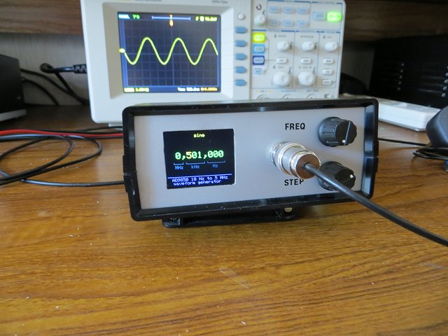
The rotary encoder conected to ATmega328 pins D2 and D3 - which triggers an interrupt routine in the software - controls the frequency which is written to the AD9833 module (and to the output). The frequency increments by a factor of x1, x10, x100, x1000 and so on. The actual increment is set using the second rotary encoder - which is software driven, rather than using the interrupt. The selected multiplier (x1, x10, etc) is indicated on the display by highlighting the corresponding digit in yellow. The rotary encoder is connected "backwards" in that rotating the knob counter-clockwise increases the increment. As a result, the highlighted digit moves to the left as the knob is rotated to the left and vice versa. Just swap D5 and D6 in the software if you prefer it the other way. The rotary encoder library is very good at spotting "illegal" switch positions due to contact bounce so additional de-bouncing hardware (or software) isn't necessary.
The Power Supply
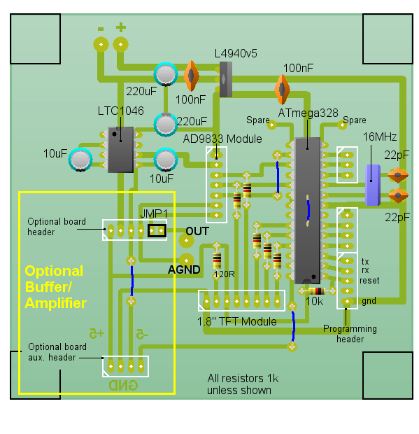
The LTC1046 5v to -5v converter, in the power supply section, provides a -5v rail derived from the +5v rail. It's not used at all in the main circuit but is available at the header for the "Optional Buffer/Amplifier Board". Most wideband OpAmps tend to require a ±5v supply so it's convenient to provide one here. I found it virtually impossible to design and test a wideband amplifier on a breadboard so it made sense to have the facility to add it as a separate PCB.
Optional Buffer/Amplifier/Filter
Although not shown in the circuit diagram, the main PCB also connects ATmega328 pin A5 to the Optional Board header. Configured as a digital output, it could, for example, be used to switch in an attenuator when SQUARE WAVE is output from the AD9833. Square waves are output at 5 volts peak to peak whereas the Sine and Triangle are only about 600mV peak to peak.I haven't yet managed to successfully build a buffer/amplifier board that hasn't introduced more noise than it was designed to cure but I've left the idea in the PCB design "just in case".
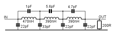
As the original idea of building this project was to compare the AD9850 and AD9833 modules, I think the AD9850 provides a cleaner output over a wider frequency range but, if the frequency is kept below 1MHz, the AD9833 has the advantage of also providing a triangular waveform. The cleaner output from the ADF9850 isn't really surprising as the AD9850 uses a 125MHz reference crystal to generate the sine wave whereas the AD9833 crystal is only 25MHz. The AD9850 module also benefits from an on-board 3-stage low-pass filter to remove any unwanted harmonics.
Example Filter
PCB Layout
Download Circuit Wizard PCB Artwork and Layout.Download PCB Artwork in PDF format.
Construction
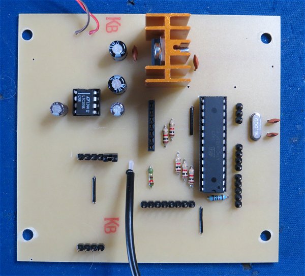
Main Components
| 1.8" TFT Display Module | Bang-good |
AD9833 DDS Module 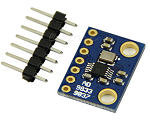 | eBay |
| 50x130x100mm enclosure | CPC |
The ATmega328 'sketch'
AD9833 DatasheetArduino Libraries:
Adafruit_GFX Library
Adafruit_ST7735 Library*
Adafruit_QDTech Library*
Rotary Encoder Library
* Use the ST7735 library if the display has an ST7735 controller chip or the QDTech library if the display uses the Samsung S6D02A1 chip.
/*
AD9833 Waveform Module vwlowen.co.uk
*/

#include <SPI.h>
#include <Rotary.h>            // Rotary encoder: https://github.com/brianlow/Rotary


#define dc   A0                // Define pins for TFT display.
#define cs   A1                //
#define rst  A2

#include <Adafruit_GFX.h>      // Core graphics library

// include Adafruit library OR QDTech library depending on the display's controller chip.

//  #include <Adafruit_ST7735.h>            // Hardware-specific library
//  Adafruit_ST7735 tft = Adafruit_ST7735(cs, dc, rst);

  #include <Adafruit_QDTech.h>              // Hardware-specific library
  Adafruit_QDTech tft = Adafruit_QDTech(cs, dc, rst);


// https://github.com/zigwart/Adafruit_QDTech


#define BLACK 0x000                         // Define the display colours we'll be using
#define BLUE 0x001F                         // so they're constants regardless of which
#define GREEN 0x07E0                        // display library we use.
#define YELLOW 0xFFE0
#define GREY 0x632C

const int SINE = 0x2000;                    // Define AD9833's waveform register value.
const int SQUARE = 0x2028;                  // When we update the frequency, we need to
const int TRIANGLE = 0x2002;                // define the waveform when we end writing.

int wave = 0;
int waveType = SINE;
int wavePin = 7;

int freqUpPin = 2;                          // Define rotary encoder pins.
int freqDownPin = 3;
int stepUpPin = 5;
int stepDownPin = 6;

const float refFreq = 25000000.0;           // On-board crystal reference frequency

const int FSYNC = 10;                       // Standard SPI pins for the AD9833 waveform generator.
const int CLK = 13;                         // CLK and DATA pins are shared with the TFT display.
const int DATA = 11;

Rotary r = Rotary(freqUpPin, freqDownPin);    // Rotary encoder for frequency connects to interrupt pins
Rotary i = Rotary(stepUpPin, stepDownPin);    // Rotart encoder for setting increment.

unsigned long freq = 1000;               // Set initial frequency.
unsigned long freqOld = freq;

unsigned long incr = 1;
unsigned long oldIncr = 1;

void setup() {

  pinMode(freqUpPin, INPUT_PULLUP);      // Set pins for rotary encoders as INPUTS and enable
  pinMode(freqDownPin, INPUT_PULLUP);    // internal pullup resistors.
  pinMode(stepUpPin, INPUT_PULLUP);
  pinMode(stepDownPin, INPUT_PULLUP);
  pinMode(wavePin, INPUT_PULLUP);

   // Can't set SPI MODE here because the display and the AD9833 use different MODES.
  SPI.begin();
  delay(50);

  // Initialize either Adafruit OR QDTech display
  //QDTech display
     tft.init();

  //Adafruit display
  // tft.initR(INITR_BLACKTAB);   // initialize a ST7735S chip, black tab

  tft.setRotation(3);
  tft.setTextWrap(false);                                  // Allow text to run off right edge

  tft.fillScreen(BLACK);
  tft.drawFastVLine(20, tft.height()-55, 4, GREY);         // Display 'static' cosmetic text.
  tft.drawFastVLine(40, tft.height()-55, 4, GREY);
  tft.drawFastVLine(47, tft.height()-55, 4, GREY);
  tft.drawFastVLine(88, tft.height()-55, 4, GREY);
  tft.drawFastVLine(95, tft.height()-55, 4, GREY);
  tft.drawFastVLine(134, tft.height()-55, 4, GREY);

  tft.drawFastHLine(20, tft.height()-52, 20, GREY);
  tft.drawFastHLine(47, tft.height()-52, 42, GREY);
  tft.drawFastHLine(95, tft.height()-52, 40, GREY);

  tft.setTextColor(GREY);
  tft.setCursor(23, tft.height()-48);
  tft.print("MHz   kHz     Hz");

  tft.setCursor(15, tft.height() -20);
  tft.setTextSize(1);
  tft.drawFastHLine(0, tft.height() - 23, tft.width()-10, BLUE);
  tft.setTextColor(BLUE);
  tft.println("AD9850 10 Hz to 5 MHz ");
  tft.print("   waveform generator");


// Configure interrupt for rotary encoder and enable.
  PCICR |= (1 << PCIE2);
  PCMSK2 |= (1 << PCINT18) | (1 << PCINT19);
  sei();

  AD9833reset();                                   // Reset AD9833 module after power-up.
  delay(50);
  AD9833setFrequency(freq, SINE);                  // Set the frequency and Sine Wave output
  updateDisplay();
}

void updateDisplay() {

  // To complicate things, the display uses SPI MODE0 but the AD9833 uses SPI MODE3 so it's
  // necessary to switch modes before each SPI transfer.
  SPI.setDataMode(SPI_MODE0);

  tft.fillRect(50, 10, 100, 12, BLACK);            // Clear text.

  tft.setTextColor(YELLOW);
  tft.setCursor(55, 10);
  tft.setTextSize(1);
  switch (waveType) {
    case SINE: tft.print("  sine"); break;
    case SQUARE: tft.print(" square"); break;
    case TRIANGLE: tft.print("triangle"); break;
  }

  tft.fillRect(25, 50, 140, 14, BLACK);           // Clear frequency numerals.
  tft.setTextColor(GREEN);
  tft.setTextSize(2);
  tft.setCursor(25, 50);
  format(freq);                                   // Show frequency in formatted form.

}

void format(unsigned long value) {

   // Break the frequency value down into individual digits & into variable 'digit'.
   // If a digit corresponds with the currently-selected x10 increment, change the
   // text colour to YELLOW. All other digits and commas are GREEN.

  unsigned long j = 1000000;

  for (int i=6; i>=0; i--) {
    int digit = (value / j) % 10;
    incr == j ? tft.setTextColor(YELLOW): tft.setTextColor(GREEN);
    tft.print(digit);
    if ((i == 6) || (i == 3)) {                  // Add commas at millions and thousands
      tft.setTextColor(GREEN);
      tft.print(",");
    }
    j /= 10;
  }
}


void loop() {

  if (oldIncr != incr) {
    updateDisplay();
    oldIncr= incr;
  }

  // Check 'increment' rotary encoder. Increase or decrease 'increment' by a factor of x10
  // if encoder has been turned.
  unsigned char result = i.process();
  if (result) {
    if (result == DIR_CW)  {if (incr < 1000000) incr *= 10;}
    if (result == DIR_CCW) {if (incr >= 10) incr /= 10;}
    updateDisplay();
  }

  // Check if push button on 'increment' rotary encoder is pushed and set Wave Type accordingly.
  if (digitalRead(wavePin) == LOW) {
    wave += 1;
    if (wave > 2) wave = 0;
    switch (wave) {
      case 0: waveType = SINE; break;
      case 1: waveType = SQUARE; break;
      case 2: waveType= TRIANGLE; break;
    }
    AD9833setFrequency(freq, waveType);     // Set AD9833 to frequency and selected wave type.
    updateDisplay();
    delay(200);
  }

  if (freq != freqOld) {                    // If frequency has changed, interrupt rotary encoder
    AD9833setFrequency(freq, waveType);     // must have been turned so update AD9833 and display.
    updateDisplay();
    freqOld = freq;                         // Remember new frequency to avoid unwanted display
  }                                         // and AD9833 updates.
}

// AD9833 documentation advises a 'Reset' on first applying power.
void AD9833reset() {
  WriteRegister(0x100);   // Write '1' to AD9833 Control register bit D8.
  delay(10);
}

// Set the frequency and waveform registers in the AD9833.
void AD9833setFrequency(long frequency, int Waveform) {

  long FreqWord = (frequency * pow(2, 28)) / refFreq;

  int MSB = (int)((FreqWord & 0xFFFC000) >> 14);    //Only lower 14 bits are used for data
  int LSB = (int)(FreqWord & 0x3FFF);

  //Set control bits 15 ande 14 to 0 and 1, respectively, for frequency register 0
  LSB |= 0x4000;
  MSB |= 0x4000;

  WriteRegister(0x2100);
  WriteRegister(LSB);                  // Write lower 16 bits to AD9833 registers
  WriteRegister(MSB);                  // Write upper 16 bits to AD9833 registers.
  WriteRegister(0xC000);               // Phase register
  WriteRegister(Waveform);             // Exit & Reset to SINE, SQUARE or TRIANGLE

}

void WriteRegister(int dat) {

  // Display and AD9833 use different SPI MODES so it has to be set for the AD9833 here.
  SPI.setDataMode(SPI_MODE2);

  digitalWrite(FSYNC, LOW);           // Set FSYNC low before writing to AD9833 registers
  delayMicroseconds(10);              // Give AD9833 time to get ready to receive data.

  SPI.transfer(highByte(dat));        // Each AD9833 register is 32 bits wide and each 16
  SPI.transfer(lowByte(dat));         // bits has to be transferred as 2 x 8-bit bytes.

  digitalWrite(FSYNC, HIGH);          //Write done. Set FSYNC high
}


// Interrupt service routine for the 'frequency' rotary encoder.

ISR(PCINT2_vect) {

  unsigned char result = r.process();
  if (result) {
    if (result == DIR_CW) {                   // Clockwise rotation so add increment to frequency
       if ((freq + incr) < 6000000) freq+=incr;

    } else {
        if (freq > incr) {                    // Counter-clockwise rotation so subtract increment
          freq -= incr;                       // from frequency unless it would result in a negative
        } else {                              // number.
          if (freq >= 1) incr /= 10;
          if (incr < 1) incr = 1;             // Compensate for math rounding error.
        }
    }
  }
}