Analogue HD & Composite Video (CVBS) Video Splitter
Ideally, I wanted a camera to feed both the CCTV recorder and the original PC video capture card. It's not usually possible to simply connect the video signal to both destinations because it nearly always results in one or both pictures being too dark or subject to interference patterns or bars.
The solution is to use an active video splitter using Op Amps to connect the single video source to more than one destination. This simple circuit only provides the two outputs that I needed (one to the CCTV recorder and one to the original PC capture device) but it could easily be extended to provide more, for example, to provide video for monitors in several rooms. Note that this project does not handle audio (if present).
The completed project has been tested with both Analogue HD and conventional Composite Video (CVBS) cameras and produces good results with both.
The Circuit
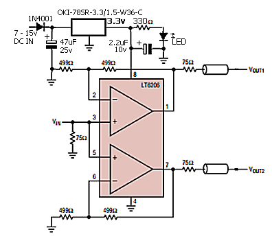
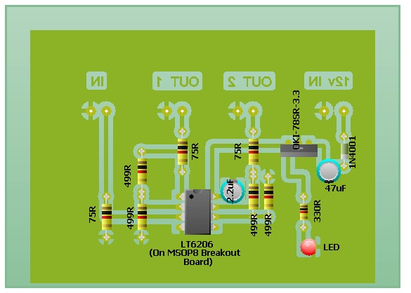
The main component is the LT2606 Dual, Single supply 100MHz Video Op Amp IC from Linear Technology. The circuit is taken straight from the LT2606 datasheet with the addition of the 3.3v power supply.
To give as wide a DC power input range as possible, I've used a 3.3v 1A DC-DC "buck" converter rather than the usual LM-series regulator. The one I used is pin-compatible with a standard LM7833 which could probably be used instead as the current taken by the circuit is very small - around 10mA. As the cost of the specified OKI-78SR-3.3/1.5-W36-C converter is relatively low and the circuit will be running continuously 24/7, I thought it worthwhile keeping the power dissipation in the regulator to the absolute minimum.
As the converter does not have any inherent DC input reverse-polarity protection, I included the 1N4001 diode in series with the input. The converter is rated at 7 to 36 volts DC input but, as I used a 25v DC capacitor on the input, the voltage should be limited to no more than about 20v DC. As I use the same power supply for the camera, I use a 12v DC input.
The odd value resistors (499 Ohms) are, perhaps surprisingly, an easily obtained, stock value.
The two 75 Ohm resistors at the right hand end of the coax (Shown on the datasheet schematic but, not on my schematic) are assumed to be the load/terminators usually provided by each destination input and are, therefore, not present in this design.
The series 75 ohm resistor and the 75 ohm load resistor form a 2:1 potential divider. As the gain of the OpAmp is 2, [ (499 ÷ 499) +1 ], the overall gain of the complete circuit is 1. (Vout = Vin).
Construction
 The only difficult part of the construction, from my point of view, is that the LT6206 is only available in a tiny MSOP8 package. I ordered two free samples
from Linear Technology and a couple of MSOP8 to DIP8 adapter boards (breakout boards) from eBay. I ruined one board by getting it too hot attempting to
clear a solder bridge causing a pad to lift from the board.
The only difficult part of the construction, from my point of view, is that the LT6206 is only available in a tiny MSOP8 package. I ordered two free samples
from Linear Technology and a couple of MSOP8 to DIP8 adapter boards (breakout boards) from eBay. I ruined one board by getting it too hot attempting to
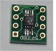
clear a solder bridge causing a pad to lift from the board.Although the soldering isn't perfect on the second attempt, it does the job and, most importantly, there are no solder bridges across the pins. To give an idea of the scale of this photo, the gap between the pads for the IC pins is less than 0.3mm.
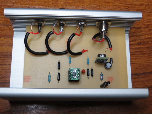
Take care with the orientation of the IC on the breakout board. Ideally, pin 1 should connect with the square pad on the breakout board but some breakout boards are double-sided, with a different IC profile on the reverse side, which makes it impossible to align pin 1 with the square pad (as in this photo). It doesn't really matter - just be aware of which is pin 1 when the breakout board is soldered to the main PCB.
Actually, as this was essentially a prototype, I didn't solder the breakout board directly to the main PCB but used an 8-pin DIP
socket on the main PCB instead. It doesn't seem to have had any detrimental effect on the picture quality at all.
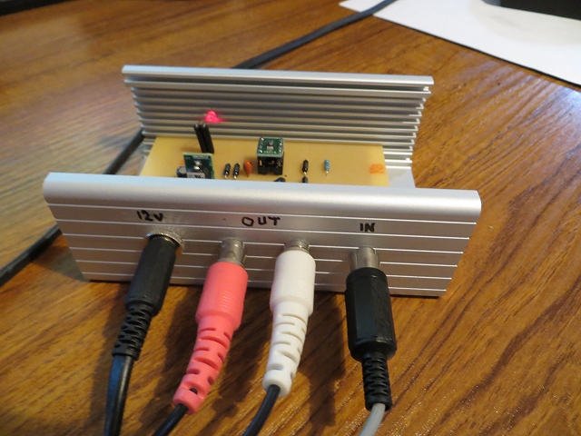
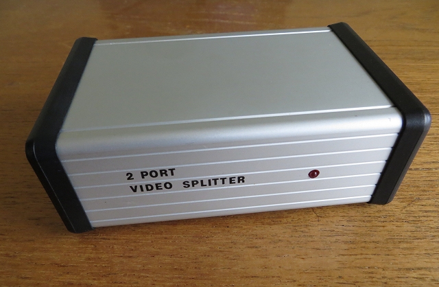
Although the PCB could be made quite a bit smaller, I already had the Hammond enclosure so it made sense to size the PCB to fit it.
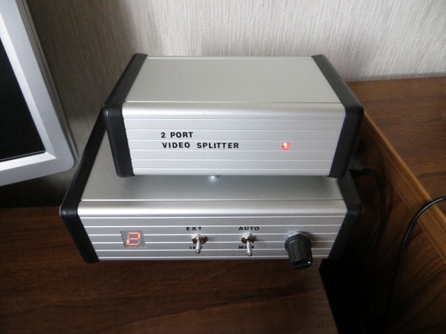
Top unit is the video splitter in use. Bottom unit is a
video switching unit
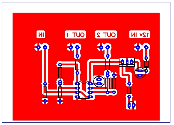
Printed Circuit Board
I used the laser printer / iron on method to make the PCB and , these days, I use the clean etching solution instead of the messy ferric chloride.
It's Di-Sodium Peroxodisulphate Hexahydrate and 400g makes up about 500ml of solution. It's available from HobbyTronics and Rapid Electronics in the UK.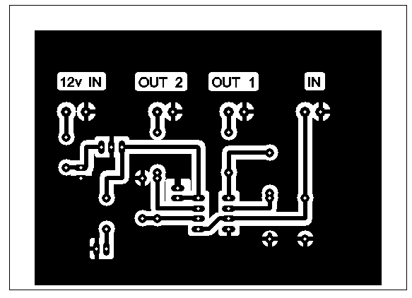
Download actual size PCB artwork in PDF format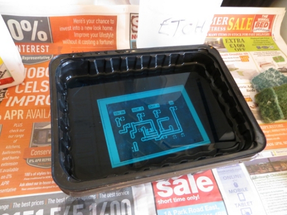
LT6206 Video Op Amp Linear Technology
Hammond Enclosure 120 x 78 x 43mm
Farnell
OKI-78SR-3.3/1.5-W36-C RS Components, Farnell
MSOP8 Breakout Board eBay 3 x RCA/Phono sockets eBay
2.1mm Panel Mounted DC socket eBay