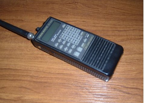
Resetting the Fairmate HP-2000
 The Fairmate HP-2000 suffers from an unfortunate bug in that, if you clear too many of it's memory channels,
it has a tendency to lock up it's processor. I fell into the trap many years ago and my scanner has been lying
idle ever since as hobbies and priorities change.
The Fairmate HP-2000 suffers from an unfortunate bug in that, if you clear too many of it's memory channels,
it has a tendency to lock up it's processor. I fell into the trap many years ago and my scanner has been lying
idle ever since as hobbies and priorities change.I'm currently having problems with my broadband ADSL connection and, as it uses frequencies in the KHz range, I dug out my scanner in order to monitor for interference - forgetting that I'd effectively "bricked" it many years ago.
A web search reveals that it's still a popular scanner in one or other of it's many guises and I decided I had nothing to lose by attempting to reset the CPU.
All references to resetting provide a warning that you follow the instructions at your own risk. Take Note!
 To reset the Fairmate HP-2000, you need to solder a temporary jumper wire across two points on the CPU board.
To get at this board, involves removing two others stacked on top, as follows.
To reset the Fairmate HP-2000, you need to solder a temporary jumper wire across two points on the CPU board.
To get at this board, involves removing two others stacked on top, as follows.
- Remove the batteries, disconnect the antenna and pull off the tuning, volume and squelch knobs.
- Remove the four small screws holding the two halves of the case together. Two are located near the shoulder-strap mounting lugs and two are in the battery compartment.
- Carefully remove the back half of the case and unplug the battery connector where it plugs into the power supply/charger board. Lay the back to one side.
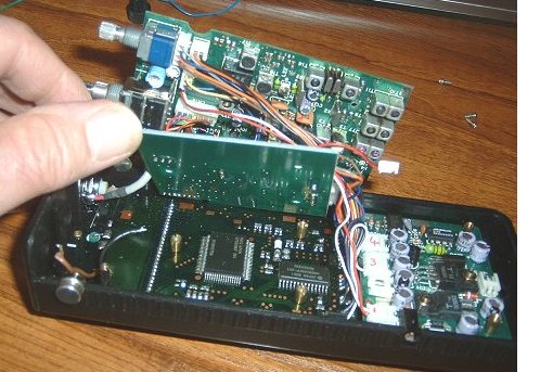
- At the top left hand corner, near the tuning knob, unsolder the brown wire from the corner of the top board.
- Uncrew the three screws holding the board in place and carefully pull the board out and down. The volume/squelch and tuning knob will come with it. "Hinge" the board as far as it will go out of the way.
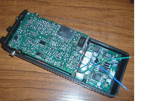
- Unsolder the black wire at the top left corner of the middle board. Uncrew the three brass stand-off pillars which hold this board in place. Carefully, hinge this board out of the way as well. It may help to unplug one or two of the connectors from this board but number their positions with a felt tip pen before you unplug them.
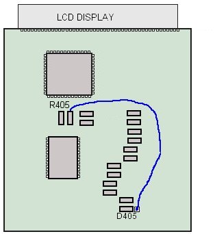 Locate components R405 and D405 and solder a thin wire between them as shown here.
For a better drawing of the CPU board, see here: Javiation.co.uk
Replace any connectors you removed and replace the middle board. Resolder the black wire. Temporarily replace the top board. Resolder the brown wire.
Replace the batteries and switch on. The display will be blank because the radio now needs re-programming.
Enter the following keystrokes exactly as shown. [v] is the down arrow key. [prog] are keys. Initially, not all keystrokes will appear on the display but, as the programming progresses, the radio becomes more responsive.
Because there may be no "feedback" from the display, press each key deliberately and carefully.
UK Programming sequence
 [bank]	1  [prog]     0.5   [limit]   44.995   [search]   556.325  [enter]
 	2  [prog]    50	    [limit]  107.995   [search]   556.325  [enter]
	3  [prog]   108	    [limit]  169.995   [search]   556.325  [enter]
	4  [prog]   170     [limit]  286.995   [search]   556.325  [enter]
	5  [prog]   287	    [limit]  599.995   [search]   249.125  [enter]
	6  [prog]   800     [limit] 1109.995   [v]	  249.125  [enter]
	7  [prog]  1110     [limit] 1300       [v]        556.325  [enter]
	8  [prog]   600     [limit]  799.995   [search]    58.075  [enter]
 Switch off. Remove the temporary wire and re-assemble the radio.
Initially, I was going to leave the termporary wire available for future use but eventually decided against it!
With thanks. The information on this page was taken from a free download from here: