The Indoor Unit - The PCB Layout
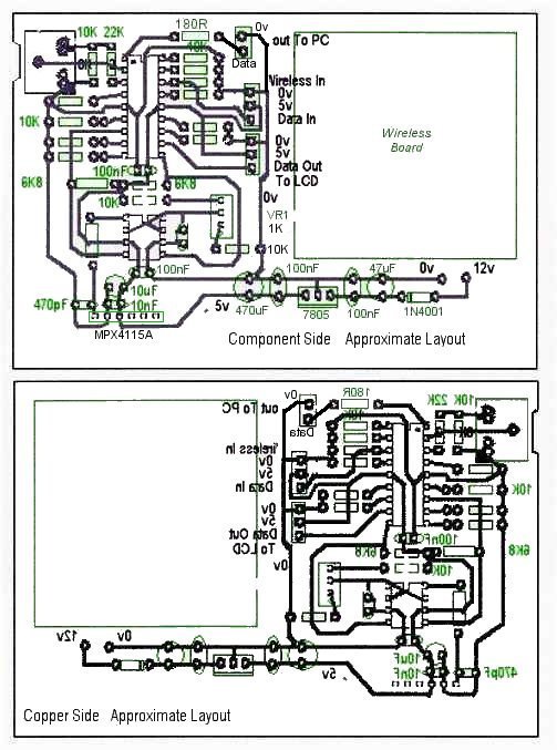
As with the PCB for the outdoor unit, I drew the layout by hand using Paintshop Pro so don't rely on the pin spacing being exact if you use a photographic or printing method to produce the PCB. I use rub-on etch-resist transfers which allows me to 'tweak' the layout and pin spacing on the actual PCB as I go along. An example of where I changed the layout can be seen at the bottom left hand corner of the copper side of the PCB where I re-routed the tracks to accomodate a PCB-mounted 12 volt power socket.
The board is slightly larger than is strictly necessary so as to fit in the grooves inside the aluminium case and to occupy the full width of the case to prevent it sliding sideways.
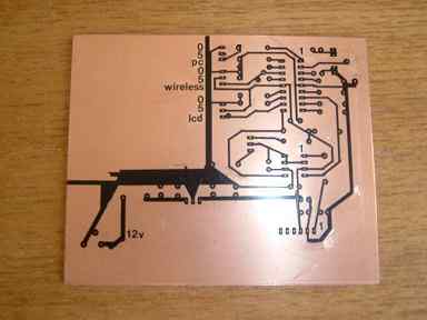
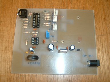
Two photos showing the PCB almost ready for the etching solution and completed with components except for the wireless receiver board and the two ICs. I used PCB header plugs to connect the main PCB to the LCD, the wireless board, the front-panel push buttons and the socket for the computer connection. The Picaxe programming socket is at the top left of the PCB; the 12v DC input socket is at the bottom right.
I deliberately made the programming socket a little "inboard" from the edge of the PCB to prevent it touching the case's metal endplate. It meant making a small "cutout" in the edge of the PCB (similar to the Picaxe project boards) to allow the plug to be inserted fully.
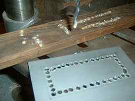
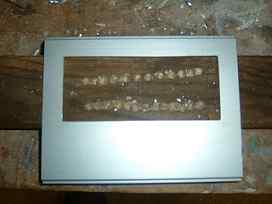
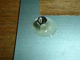
The aluminium case is from Rapid Electronics. The cut-out for the LCD display is made by chain-drilling the case and filing the hole until the LCD is an exact fit. An M3 x 6mm hex pillar is Araldited to each inside corner as mounting posts for the LCD, to avoid unsightly screw heads showing on the outside.
 |  | 
|
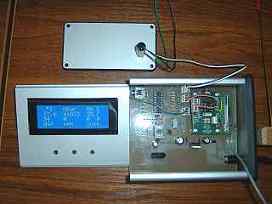 | 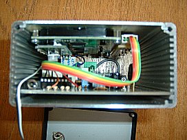 |
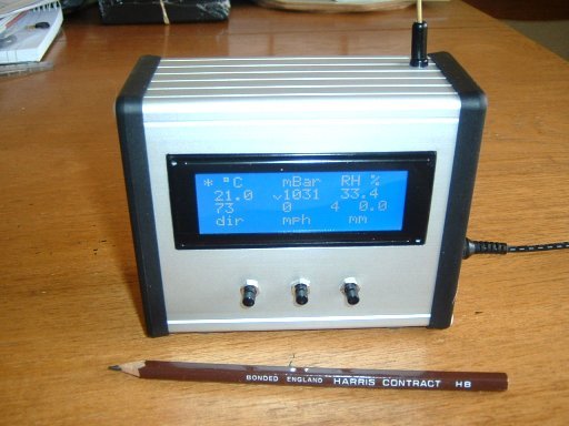
The far left photo shows everything installed into the case and powered up. Three push buttons to be fitted to the front of the case
were still "in the post" when I took these photos. The near photo shows the case closed with one end removed. The pin-header connector on the Wireless board makes it a tight squeeze. I had to remove the 5-pin right-angle connector from the LCD's serial board and solder the "jump lead" from the connector on the main PCB, directly to the LCD serial board. |