The Outdoor Unit - Circuit Diagram
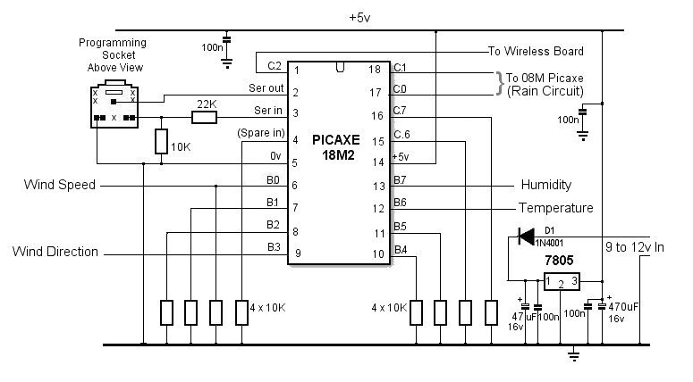
This circuit and the circuit for the 08M Picaxe for the rain sensor are built on the same PCB. The unit is supplied from a 12v 7AH lead acid battery which, currently, is being trickle-charged from the mains. Ultimately, I intend to add a Solar Panel to keep the battery charged. The 7805 voltage regulator supplies both Picaxes, all the remote sensors and the wireless module with 5 volts.
I used an RF Connect kit from techsupplies.co.uk for the wireless link with a 433MHz transmitter/receiver pair from Bitsbox.co.uk. The Connect Kit contains a pair of specially programmed PIC chips which employ Manchester encoding/decoding and CRC checks on the serial data stream to make the wireless link as reliable as possible. There's quite a lot of 70cms (433MHz) radio activity near my location so it seemed sensible to try to make the wireless link as immune as possible from external interference.
As the RF Connect kit and the wireless modules had proven themselves to be reliable during testing, there seemed little point in disturbing them so the complete RF Connect board is mounted on a corner of our Outdoor Unit board.
The Outdoor Unit - The PCB Layout
The Outdoor Unit's PCB holds the rain gauge's 08M Picaxe together with the main 18M2. Each has its own programming socket and associated resistors. The 5 volts regulated power supply and the Wireless Module are together at one end. Separate connectors, each with their own +5v and 0v, are provided for each sensor - except for the temperature/humidity connections which share their +5v and 0v).
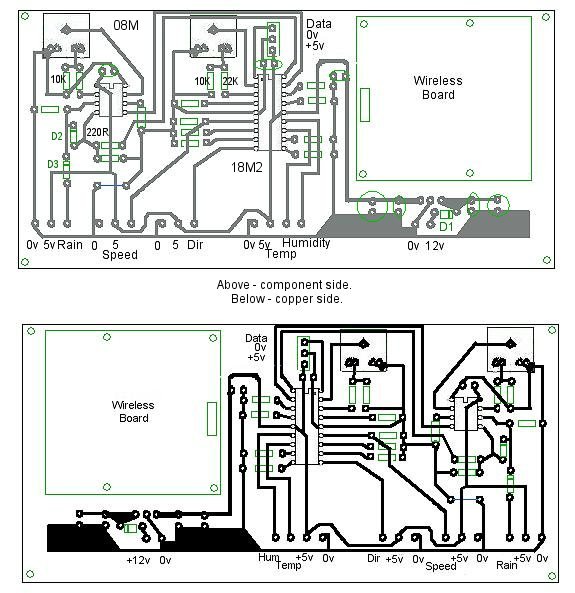
 | Please note that I drew the layout shown above by hand in Paintshop Pro so I cannot guarantee the accuracy of the pin spacing.
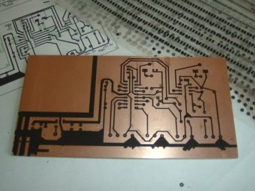
I use Seno etch resist transfers. I find it relatively quick to make a board of this size and, although I follow the Paintshop Pro layout, I can make any minor adjustments to the layout that may be required, as I go along. This photo shows the board almost completed. The large area at the bottom and the square area under the Wireless Module are yet to be masked with PVC tape. Tape makes good etch resist and, by not unnecessarily etching large areas of copper, the useful life of the Ferric Chloride etching solution is prolonged. In this instance, it's probably good practice to leave the copper 'ground plane' under the wireless board anyway. |
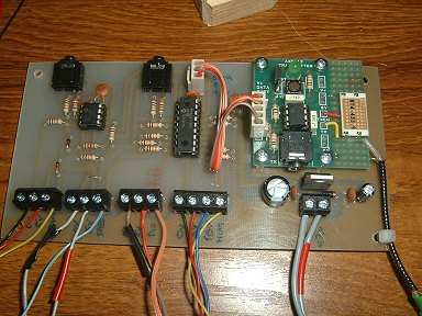
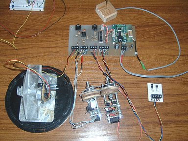
These photos show the completed Outdoor Unit PCB, connected to all the outdoor sensors and is up and running - albeit with the sensors on short connecting leads. The cable tie at the bottom right (in the left hand photo) is temporarily taking the strain off the antenna cable until the unit is mounted in its final IP65 (weather resistant) box. The antenna cable is high quality 50 ohm cable that I had in my spares box but, as it's quite stiff, I may change it for something a bit more flexible.
Update: Once the PCB was in the box, the antenna connection was very short so I used an unscreened piece of wire to the antenna terminal post.
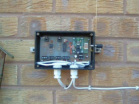
Outdoor unit attached to the garage wall.
Hopefully, I won't need access to the Picaxe programming sockets too often. It would have been a shame to spoil the IP65 integrity of the box by drilling "access holes" in the top of the box.. If the Picaxes should need reprogramming, it will only be a case of loosening the PCB mounting screws and tilting the board forward an inch - or even removing the Picaxe and taking it indoors!