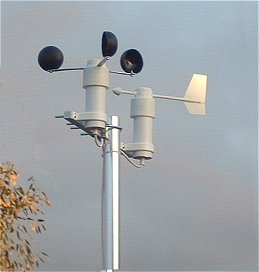
This video was taken in December 2015, nearly 5 years after the still photo and the sensors are weathering quite well.
Mechanical Parts
The windspeed and wind direction sensors are a combination of mechanical and electronic parts. The "core" of the mechanical construction is identical for both sensors. These drawings detail the mechanical construction of the windspeed sensor.
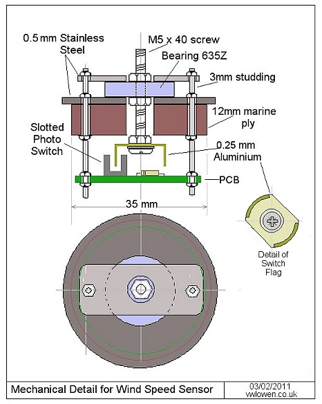
The 12mm marine ply disc is a "snug" fit inside the PVC pipe and the stainless steel disc sits on top of the end of the pipe. The shielded bearing is super-glued to the stainless steel disc in addition to being held down firmly with the stainless retaining plate.
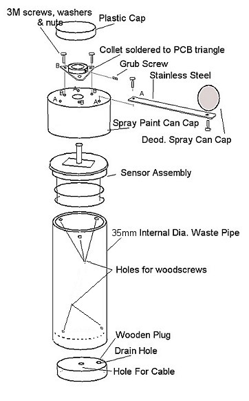
The wooden plug at the bottom end of the pipe is positioned so that there is a 5mm 'lip' at the end of the pipe so that rain running down the outside will drip off.
The rotating hub is a cap from a can of spray paint and sits over the PVC pipe. There's about 1.5mm clearance all round between the cap and the pipe - plenty of clearance to apply a layer of self-amalgamating tape over the top edge of the pipe to seal the joint between the pipe and the "sensor assembly".
 |
A 5mm zinc-plated collet is soldered to a small triangle of fibre-glass PCB which is attached to the top of the
cap using three 3mm screws, washers and nuts.
(Note that the wind direction sensor uses a small square of PCB, instead of the triangle, and the 'arrow' is attached by using
longer screws across one of the square's diagonals.)
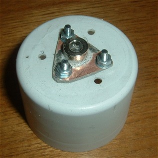
Once everything is fully assembled and tightened, a plastic milk bottle top is fixed to the top of the assembly using outdoor sealant. Hopefully, this will provide a waterproof seal while still allowing the rotor to be removed for maintenance in the future. The three remaining holes in the photograph are to attach the arms for the cups. As there is only enough space for one screw in each arm, the arms are super-glued in addition to the screws. After studying the results of some research into cup-shaped anemometers I decided to simply use measurements that "looked right" ! Longer arms give a more linear rotational speed relative to windspeed but have more initial inertia to overcome. With the anemometer mounted outside, the rotor turns with barely a hint of a breeze. The arms are 80mm long giving a turning radius to the centre of each cup of 95mm. The cups are 50mm inside diameter.
|
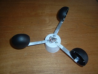 |  |
For the cups themselves, I'm currently using three tops from deoderant spays. After a bit of trimming, they are almost perfectly hemi-spherical.
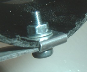
I'm not sure how robust they'll be so I've made them easy to replace by attaching them to the arms using screws and a small piece of aluminium wrapped around to help stop them coming loose or twisting and to provide a bit of additional strength. |
The Anemometer Electronics
 |
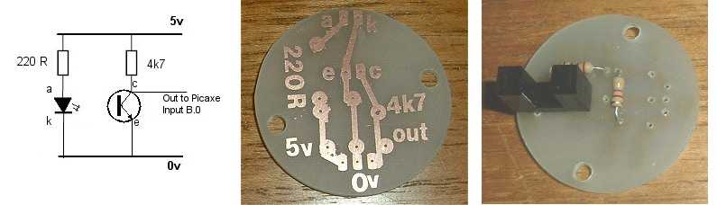
The electronics for the windspeed sensor consists of just a Transistor Output Opto-Switch
and two resistors. These are mounted on a small disc PCB about 32mm in diameter. It's deliberately a loose fit in the
pipe so that, should any moisture build up inside, it will be able to run down the inside wall of the pipe clear of
the PCB. The pinout of opto-switches seems to be fairly standard but check the datasheet of the one you choose! Some types won't work with the standard Picaxe input unless the usual 10k pulldown resistor is removed. Not shown in the 'mechanical detail' drawing above, the second (lower) PCB simply holds a three-way terminal block for the outgoing connections. |
Calibration of the Anemometer
 The anemometer is one of three instruments that needs calibrating - the others being the rain gauge and the barometric pressure sensor (which is located in the indoor unit). The anemometer sensor
provides two pulses per revolution. I was reluctant to add more 'blades' to the aluminium flag for the opto-sensor in case the
pulses became too short and were missed by the Picaxe input at higher speeds.
The anemometer is one of three instruments that needs calibrating - the others being the rain gauge and the barometric pressure sensor (which is located in the indoor unit). The anemometer sensor
provides two pulses per revolution. I was reluctant to add more 'blades' to the aluminium flag for the opto-sensor in case the
pulses became too short and were missed by the Picaxe input at higher speeds.In the simple "sequential" system that I aimed for (in which each sensor is 'scanned' in turn), there has to be a compromise between the length of time devoted to each sensor (in this case, counting pulses) and the responsiveness of the overall system. Ideally, I wanted a complete cycle to take less than two or three seconds.
An alternative to counting the pulses for a fixed period of time is to use the 'pulsin' command instead to measure the actual time taken for the aluminium flag to pass the opto-switch.
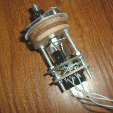
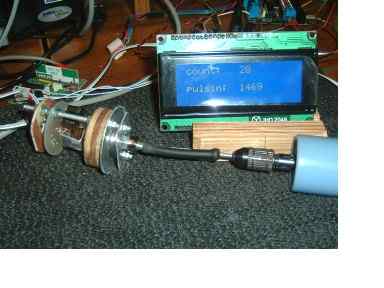
This photo shows an early test using a small variable speed motor to drive the anemometer and display the results on an LCD. As there are two "flags" per revolution (the widths of which are likely to be slightly different), the program code reads pulsin twice and takes the average.
For some reason, the pulse-length seemed to be reducing exponentially as the speed increased. As a result, counting the pulses seemed
the simpler approach (See graph).
 	  ; LCD-specific commands shown in blue

          hsersetup B9600_4, %10000 			 ; Use LCD Pin 1, no hserin
  	  hserout 0, (13) : pause 100           	 ; Initialize LCD
 	  hserout 0, (13) : pause 100
 	  hserout 0, (13) : pause 100
 	  pause 500
 	  hserout 0, ("ac1", 13)  			 ; Clear display
 	  pause 50
 	  hserout 0, ("acc", 13)
  	  hserout 0, ("ac81", 13, "adcount:  ", 13)	 ; Print the headings
 	  pause 10
  	  hserout 0, ("ac95", 13, "adpulsin: ", 13)	 ; Print the headings
  	  pause 10

	do
 	  count C.2, 1000, w0				 ; Count the pulses (two per rev)

  	  w1 = 0
 	  for b8 = 1 to 2 				 ; Measure pulse length twice
   	    pulsin C.2, 1, w2				 ; per rev and...
  	    w1 = w1 + w2
 	  next
  	  w1 = w1 / 2					 ; ...calculate average

 	  hserout 0, ("ac89", 13, "ad ", #w0, "   ", 13) ;Print the count value
 	  hserout 0, ("ac9d", 13, "ad ", #w1, "   ", 13) ;Print the pulse-length value
 	  pause 100

	loop
I was hoping to calibrate the anemometer by driving it along in the car but time became a limiting factor and, unfortunately, the opportunity never arose. I live in a relatively flat location with an airport only a few miles away so I should, hopefully, be able to calibrate it by comparing my readings with the airport's.
Meanwhile, as a starting point, I'm using the following. I'm taking 100% efficiency as the baseline because adding a quessed factor would only complicate comparisons with the airport weather. I had expected there to be a 3 or 4 mph offset to factor in as the sensor overcomes the initial inertia but, as noted above, the anemometer rotates with barely a hint of a breeze:
IF we had 100% efficiency and the cups rotated at the same speed as the wind, then:

Radius of the rotor   = 3.75"
Diameter of the rotor = 7.5"
                      = 0.625 feet

Circumference of rotor path (πD) = 1.9642 ft

         1 ft per minute   = 0.0113636 mph,
therefore, 1.9642 ft/min   = 1 rpm = 0.02232 mph
and,               1 mph   = 1 / 0.02232 rpm

                   1 mph   = 44.8 rpm

                    ?mph   = rpm / 44.8

                           = (revs per sec * 60) / 44.8

As there are two pulses per rev,

                 ?mph      = (pulses per sec * 30) / 44.8

                           = (pulses per sec * 300) / 448