Note: the latest 18-pin project boards have PCB pads brought out between the Picaxe and the Darlington chip so this modification will no longer be necessary. CHI030A.
Despite having an interest in electronics since I was about 10 years of age, I've only recently become aware of a "spin-off" from the PICmicro® microcontroller ICs. I'd looked at those several years ago but had never really found the time to devote to what seemed like quite an intensive learning curve. I'd programmed 2708 EPROMS (a massive 1KB x 8-bit) in the past but the idea of separate programming hardware for PICmicro chips somewhow seemed a retrograde step.
What I didn't know, until recently, is that someone else must have thought the same! PICAXE® microcontroller ICs start life as conventional PICmicro microcontroller ICs but the manufacturer has pre-programmed them with "bootstrap" firmware which allows them to be programmed in situ (without removing them from the final circuit board) using nothing more than a 3.5mm stereo socket, a couple of resistors and some free programming/editing software.
To gain some experience with these chips, I bought an 18M2 Starter Pack. Basically, the pack includes everything you need to get started, including a compact printed circuit board holding the 18M2 chip and a ULN2803 - 8 Darlington drivers in a single IC. The ULN2803 "protects" the PICAXE chip's outputs and allows it to switch more current.
Although useful, the ULN2803 can occasionally get in the way because sometimes direct access to the PICAXE's outputs is required - for example, when driving a radio control servo or using a pin for serial output. Although a dedicated circuit board would probably be built for final projects, it's useful to test parts of the final project using the board supplied with the starter pack.
One solution is to remove the ULN2803 and replace it with a simple DIL header. A 16-pin one is all that's required because pins 9 and 10 are the chip's supply and wouldn't be used. Fortunately, the ULN2803's pinout is such that opposite pins on the header can simply be strapped across with a piece of wire - or a 330 ohm resistor - except pins 9 and 10, which are 0v and +5v.
I wanted the option to have outputs direct from the PICAXE chip or from the ULN2803 and devised a simple "breakout board" which provides 8 outputs and 0v directly from the PICAXE. (To be strictly accurate, they're picked up from the inputs to the ULN2830). The existing 8 outputs from the ULN2803 are unaffected although it's probably not a good idea to use any particular output twice.
I'm sure a suitable long-legged IC socket is available for this modification but it would have been a case of trial and error. With postal deliveries delayed due to the holiday season and bad weather, I wanted to press ahead with parts I already had in my bits box.
 |  | 
|
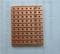
Cut a piece of veroboard, 9 copper strips x 7 holes and cut the tracks as shown in the left photo. In my enthusiasm to see if the idea would work, I ruined my first attempt because I forgot to cut the tracks. As the board is soldered copper side up, it's impossible to cut the tracks once the socket is in place!
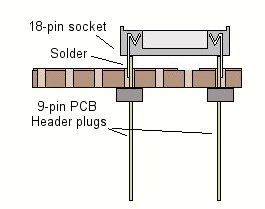
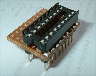
The holes in the Veroboard are easily big enough for the header pin (from below) and the IC socket pin (from above). It's a bit fiddly to assemble but, once the header pins and socket are in place, the socket sits on top of the header pins and leaves about a 0.5mm gap between the top (copper) side of the board and the underside of the socket. Just enough space to get a small soldering iron tip in and solder the socket and the header to the copper strip at each hole.
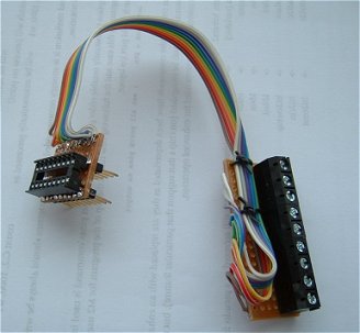 |  |
Cut another strip of Veroboard, 18 copper strips x about 7 holes and solder a 9-way terminal block (8 outputs and 0v) along one edge. Join the two boards together with a short length of ribbon cable. On the "socket board", I just soldered the wires to the copper without threading them through the holes otherwise there's a risk of the wires touching the pins on the 18M2 PICAXE chip below. I tied the cable down to both pieces of Veroboard to reduce the strain on the solder connections.
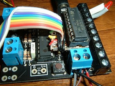
Remove the ULN2803 from the 18M2 Project Board and insert it into our new socket. Insert our board into the vacated socket with the ribbon cable on the side closest to the PICAXE chip. Job done!
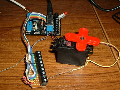
The photo below shows an LED being switched from the ULN2803 (output B.7 and +5v) and the pulse input of a servo being controlled directly from the PICAXE (output B.0 and 0v).