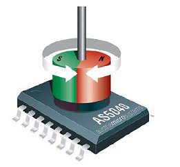
 The datasheet describes the AS5040 as a contactless magnetic rotary encoder for accurate angular measurement over a full turn of 360°.
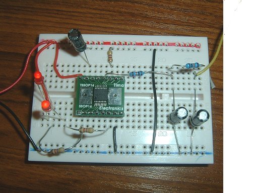
It's only available (in the UK) in an SSOP-16 package and neither my soldering skills nor my eyesight are up to the job of handling chips this small. I've been using a small company called Tirna Electronics to mount small chips on IC adapter (breakout) boards for a very reasonable cost. The company also offers to source the component from RS Components which helps to avoid RS's minimum purchase limit.
The data is output in a number of formats, some easier to understand than others. The PWM output provides pulse widths from 1µS at 0 ° through to 1023µS at 359°. I'm using an 18M2 Picaxe which has a maximum pulsin resolution of 1.25µS when clocked with a setfreq m32 so I needed to use one of the other output modes.
The PWM / Analogue Output
The datasheet contains an example of feeding the PWM output into a passive low-pass RC filter to produce an analogue output. It proved to be reasonably accurate except for a dead spot between about 330 and 359 degrees. I wasn't looking for super-fast response times so I was able to increase the suggested values in the RC filter. It's possible their suggested minimum values would produce more accuracy. See the graph on the next page showing the analogue output plotted against actual rotation.
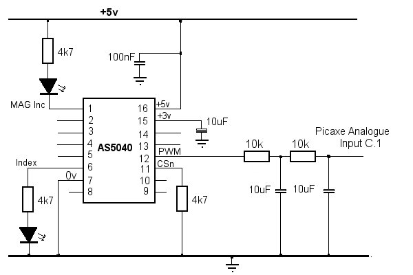 The AS5040 operates at either 3 volts or 5 volts by applying power
to the appropriate pin. If powered by 5 volts (as here), the 3v pin must be buffered by a 2.2 to 10 µF capacitor.
The AS5040 operates at either 3 volts or 5 volts by applying power
to the appropriate pin. If powered by 5 volts (as here), the 3v pin must be buffered by a 2.2 to 10 µF capacitor.
The 'Index' output at pin 6 provides a "zero" reference point. It is capable of passing 4mA maximum at 5 volts so I erred on the side of caution with the LED series resistor. The LED I used easily lit with a 4k7 resistor (approximately 1mA).
Pins 1 and 2 provide outputs to indicate if the magnetic field is increasing or decreasing. Ideally, both LEDs should not be lit. These are open source outputs capable of 4mA at 5v so, again, I used as high a value of resistor as would light my LED.
do
  readadc10 C.1, w4	;Read analogue from AS5040
  w5 = w4 * 64 / 182	;Convert to 0 - 359
  debug 		;Show in Prog/Editor
  pause 100
loop
The SSI Output
Three pins on the AS5040 are used to provide an SSI interface. It seemed likely that it would be more accurate than the analogue output so it was time to find out.... "