Reports vary about how noisy the case cooling fan is in the Humax PVR9200t. Although a recent design-change means the fan no longer runs when the box is in 'Standby', many people choose to leave the box in 'Running' mode otherwise the EPG loses its information and can take a long time to re-populate - especially if the box is tuned to a non-BBC station.
With the box switched on (ie Running) but not actually in use, the noise from the fan can become obtrusive in an otherwise quiet living room or bedroom. Some people have disconnected the fan entirely and others have fitted a commercially available variable resistor unit which provides a reduced - but fixed - fan speed.
I wanted the best of both worlds so have designed and fitted a small unit which simply plugs in between the fan and its connector on the motherboard. Now, the fan is stationary much of the time and only starts spinning as the temperature of the box increases - the warmer the box gets, the faster the fan runs. As it simply plugs in, the modification is completely reversible.
Please note that I cannot undertake to make one of these units for you, so please don't ask.
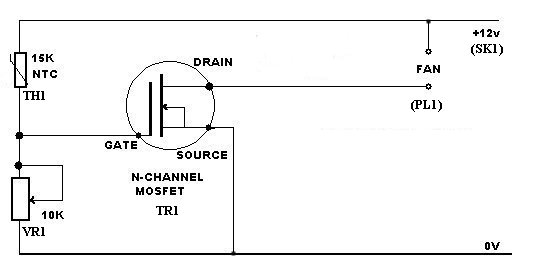 | The circuit diagram of the temperature control unit. | |||||||||||||||||||||
| Parts List | |||||||||||||||||||||
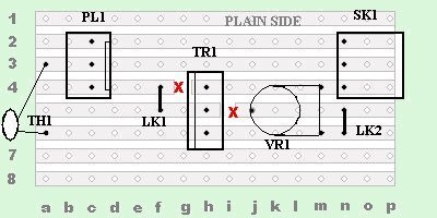 | The components are soldered to a small piece of Veroboard. LK1 and LK2 are short wire links. | |||||||||||||||||||||
 | Track side of the Veroboard. Very important - Note the track breaks in the Veroboard at locations 4g and 5i. Twist a small drill between your fingers to cut the copper tracks. | |||||||||||||||||||||
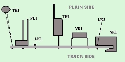 | Side view showing the parts placement. Note the socket (SK1) hooks around the edge of the board so take some time before cutting the veroboard to length to ensure the socket fits snugly. | |||||||||||||||||||||
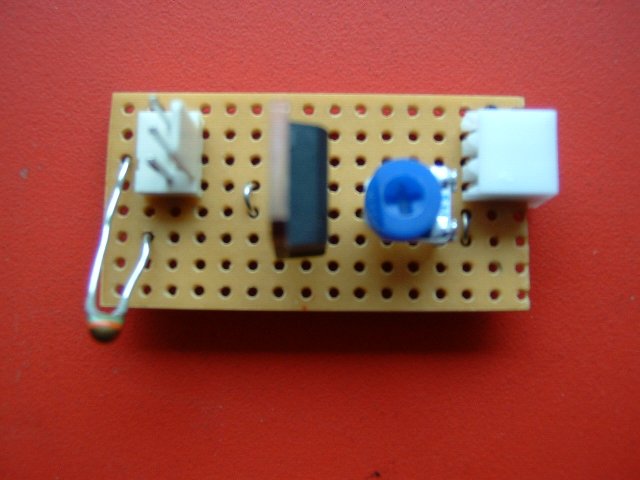 | This photo shows the actual unit. The component at the bottom left is the
temperature sensor (TH1). I left the leads long so as to position it in 'clear air' to monitor the airflow in
the box. Try to keep the sensor out of the direct air flow from the fan and away from TR1.
(I'm undecided as to which part of the Humax box is the most temperature-critical - the Hard Drive, which gets hot with extended use,
a component with a heatsink on the Power Supply or the main processor. | |||||||||||||||||||||
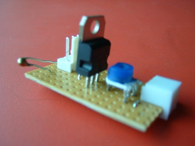 | Another view of the unit. Solder each component in turn. I suggest the following order: LK1, LK2, SK1, VR1,PL1, TR1, TH1. Soldering in this order makes it easier to hold each component in place when you turn the board over to solder it. Inspect your solder joints carefully to ensure you haven't accidentally bridged between adjacent tracks with solder. You'll find more soldering tips (for a different project) here. | |||||||||||||||||||||
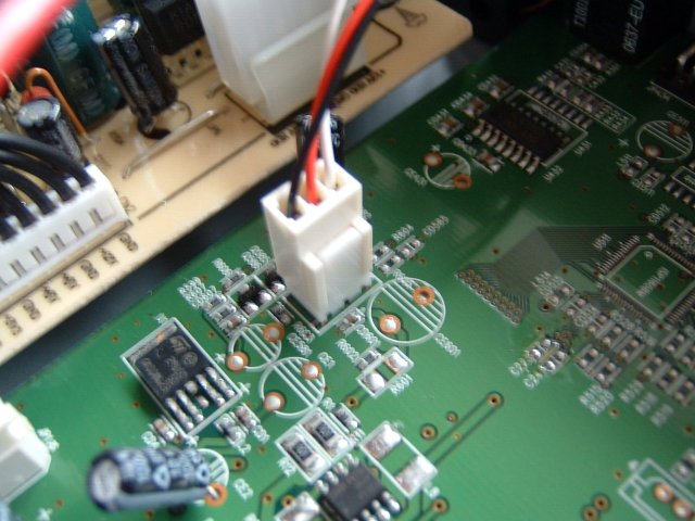 | Disconnect the Humax box from the mains before removing its cover. This photo shows the original position of the fan's power connector. | |||||||||||||||||||||
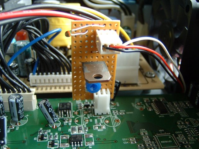 |
Unplug the fan connector from the Humax main board and plug it into the top connector on our
circuit. Then plug our circuit into the Humax main board. The Maplin connector (SK1) does not have any alignment guides
so make sure the 3 pins on the main board plug line up with SK1 correctly. The potentiometr (VR1) is adjusted so that the fan runs slowly when the box is cool. Don't forget that later versions of the 9200t only operate the fan when the box is turned on.
Beware of lethal voltages in the Humax box!! Disconnect from the mains before making each
adjustment to the potentiometer. | |||||||||||||||||||||
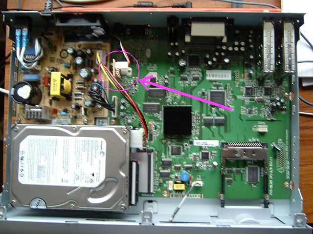 | Overall view inside the Humax showing the location of the fan connector and the new circuit board. Note the unshielded power supply board immediately to the left. |