Rechargeable Battery Capacity Tester (v2.2)
V2.1 ~ October 2019
V2.2b ~ August 2021
I seem to be using more and more rechargeable Lithium-Ion and Lithium-Polymer batteries for my portable projects these days. One problem with getting them from the Far East (either directly or through eBay) is that they tend to be of unknown quality. What's advertised as, say, 2000mAh capacity is generally lower. Depending on the application, something in the region of 1500mAh might be acceptable but they're sometimes so bad, the actual capacity is nearer 200 or 300 mAh.
So, I built this capacity tester for a few reasons: To satisfy myself that a battery would do the job in the first place and to be able to test it later if I suspected it's useful life was coming to an end. But also to be able to obtain documented proof of a battery's capacity in the (rare) event that a seller proves to be less than co-operative in accepting a return.
Design Considerations & Limitations
The design is based on the well-known constant current MOSFET circuit shown on Dave Jones' EEVblog. The actual battery capacity testing is based on another of Dave Jones' videos, shown here (about 10 minutes, 44 seconds in).Although his (professional) battery load tester was capable of providing a 5 amp load, like his constant current circuit, my battery load tester is limited to around 1.1 amps. This is mainly due to the relatively low lithium battery voltage (4.2V fully charged) providing the "driving force" for the load.
For the size of lithium batteries I use (typically around 1000 to 2000 mAh capacity), this represents a load of between 1C and 0.5C. Although this isn't particularly putting the battery "through its paces", it's 4 or 5 times the load I will typically require so I regard it as an adequate test for my purposes.
The PC Software
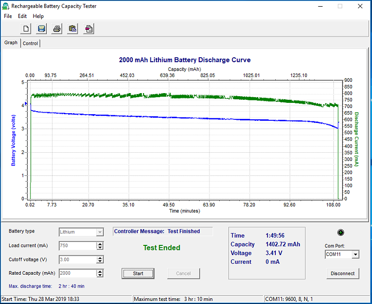
Although the battery capacity tester is able to test a battery and display its total capacity as a stand-alone unit, it works much better with a small Windows application I've written - very similar in concept to the software shown in Dave Jones' video.
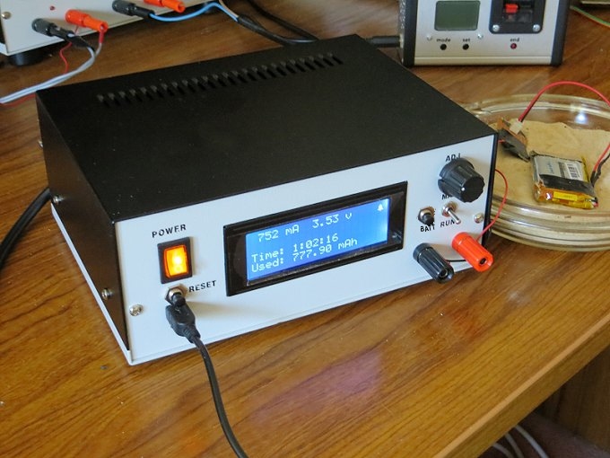
The image above shows a 2000mAh battery under test. Although only given a relatively light load of 750mA, its capacity is shown as 1402mAh which is acceptable (to me). I'd set the tester to end the test when the battery voltage fell to 3.0 volts which you can see as the blue line in the image above. The voltage rose again naturally to 3.42V as soon as the Tester removed the 750mA load current.
When the software is coupled to the battery tester hardware through a USB port, the entire capacity/load test is performed through the software which provides graphical "evidence" of the battery's performance during the discharge and can subsequently save the graph as an image (in PNG, JPEG or BMP format) or export the data as a CSV file for use with a spreadsheet application, such as Excel.
Following a suggestion and help with debugging from Paul at www.paulvdiyblogs.net, the PC software has been modified to allow other battery types (Ni-MH, Ni-Cd and Lead Acid) to be tested in addition to Lithium.
A 5 volt fan was added to version 2 because the MOSFET dissipated a lot of heat when testing Lead Acid batteries at high load currents.
You can download the Windows program here (version 2.2c).
Note: The Windows program allows you to set a maximum of 2,500mA load current as this is consistent with the design and components I've specified. The maximum load current can be changed in the BatteryTester.ini file which can be found in the same folder as the executable, BatteryTester.exe.
To adust the maximum allowable value, close the program and edit the line:
MaxCurrent=2500
Circuit Diagram
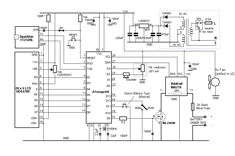
The battery under test is connected to the terminals shown bottom, right, in the diagram above. The main (high current) circuit is shown in bold. Current from the battery passes through a 2A quick blow fuse to the V+ terminal of the Adafruit INA219 high-side current sensor and through the internal 0.1 ohm current sensing resistor. It leaves the sensor on its V- terminal and passes through the IRL2203N MOSFET back to the negative side of the battery.
The current is controlled by varying the voltage on the MOSFET's gate using a 10-bit PWM signal from pin 15 (D9) on the ATmega328. The choice of MOSFET seems fairly critical. It needs to have a low gate threshold voltage but, unfortunately, this specification seems fairly "wide" on most MOSFETS, datasheets often giving a range of between 1 and 3 volts or more. The IRL2203N provided enough current for my needs. You may want to experiment with other power MOSFETS to give greater current with the available Drain voltage - ie 3.7 volts or so with the fully charged lithium battery under test.
The Atmega328 software uses a 3rd party library to provide a 10-bit DAC output (ie 0 - 1023) instead of the 'native' 8-bit (0 -255). One limitation is that the ATmega328 pin 16 (D10) cannot be used as a conventional I/O pin but, in this project, D10 isn't used at all.
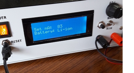 The desired ("target") current is programmed into the ATmega328 in one of two ways: With the MAN/RUN toggle switch set to
the MAN position when the tester is RESET, the 10k multi-turn potentiometer provides a voltage between 0 and 5 volts to the ATmega328 analogue pin
26 (A3). The program sets a target current between 0 and 1500mA depending on the setting of the multi-turn pot, the value being
displayed on the 20 x 4 Liquid Crystal Display.
The desired ("target") current is programmed into the ATmega328 in one of two ways: With the MAN/RUN toggle switch set to
the MAN position when the tester is RESET, the 10k multi-turn potentiometer provides a voltage between 0 and 5 volts to the ATmega328 analogue pin
26 (A3). The program sets a target current between 0 and 1500mA depending on the setting of the multi-turn pot, the value being
displayed on the 20 x 4 Liquid Crystal Display.
In Manual mode, the type of battery is selected with the push button connected to input D11. The correct "safe" cutoff voltage is set automatically for each battery type.
Once the battery type and desired load current have been set, the MAN/RUN switch is flicked to RUN. The LCD display will show the chosen settings for approximately 5 seconds and then the PWM output at D9 will ramp up to increase the IRL2203N gate voltage until the current, as measured by the INA219 sensor reaches the target value. The PWM output then continues to adjust the current for as long as there is enough battery voltage available to maintain it. Eventually, the battery voltage will fall below the critical cut-off point (fixed at 3.0v), the current will be terminated and the test will end.
The current is monitored continuously while the test is running. The instantaneous used-mAh is calculated, added to the total and displayed on the LCD as a running total of mAh capacity.
As there are enough spare outputs on the ATmega328, I opted to connect the LCD in parallel mode rather than using a serial backpack. Using a serial connection could, potentially, slow the program loop which could be detrimental to keeping good control over the target current.
Computer Control
When connected to a computer USB port through the Spakfun FT232RL board, the ATmega328 is able to communicate with a specially-written program running on the computer. If the MAN/RUN switch is in the RUN position when the tester is RESET, the computer takes control and is able to set the target current (0 to 1500mA - as when operating manually), but is also able to control the desired battery safety cut-off voltage and calcualte the maximum expected duration for the test in order to terminate the test if the expected maximum time is exceeded by 30 minutes.The safe cut-off voltage for each battery type is set automatically when the battery type is selected. Although not recommended, the facility is provided to over-ride the default setting in case you want to check the battery's internal protection circuit (if any). You can over-ride the default cut-off voltage (up and down) in 0.05 volt increments. Use at your own risk!
Of course the main point about using the computer program is to provide the graphical output which plots the familiar battery voltage and load current discharge curves as supplied by many battery manufacturers.
As a convenience, the computer program is able to reset the ATmega328 by pulsing the RS232 DTR signal low via a 100nF capacitor and JP1 (in the circuit diagram). Sometimes USB ports can interact with each other so, if the ATmega328 inconveniently resets when other computer USB ports are in use, JP1 may be removed to prevent this happening. I wired it as an internal jumper but it could easily be brought out to a panel-mounted switch if you wanted the best of both worlds.
Power Supply
I decided to provide the project with its own 240v AC to 5v DC power supply rather than tying up a 12v adapter. If you're not confident handling mains voltages, simply provide 9v to 12v DC to the input of the L4940v5 LDO regulator and omit the two 1N4001 diodes and the mains transformer.
Use good quality screw-in type panel fuses and ensure that the design is such that, when removing the fuse holder, it is well clear of live internal contacts before there is sufficient clearance to be able to touch the fuse (or the holder's metal parts) with your fingers.
The mains earth (ground) lead is connected to the enclosure through the transformer mounting bolt.
Note that any parts of the enclosure that are attached separately (such as the front & rear panels and the top attached with self-tapping screws, for example) should have their own earth wire back to the same transformer mounting bolt. Do not rely on the self-tapping screws for earth continuity. Try to leave the incoming earth conductor longer than the live and neutral conductors so that, if the cable does get forcibly pulled, the earth will be the last conductor to break.
All exposed mains-voltage connections - to the illuminated switch, the fuseholder and the transformer - must be insulated with heat-shrink sleeving and/or access prevented with insulating covers. It should not be possible to make contact with any high voltage connections - even with the top cover removed - without a determined and conscious effort!
The mains cable entering through the rear panel must be protected from chafing with a rubber grommet and the cable must be clamped against moving inside the enclosure to prevent the connections being pulled or twisted and to prevent the grommet being pulled from its hole. Don't knot the cable because (a) it doesn't stop the cable twisting, (b) the conductors are forced with great pressure towards each other through their insulation which can damage the insulation over time resulting in the conductors shorting and (c) it looks so unprofessional!
Despite what commercial products may do, do not use the printed circuit board for any mains voltage part of the circuit.